What a Tripping RCBO Is Actually Telling You
An RCBO integrates two independent protection functions into a single modular device: residual current detection (earth leakage protection per IEC 61009-1) and overcurrent protection (short-circuit and overload per IEC 60898-1). When an RCBO trips, it is signaling that one of these two protection mechanisms has operated — but the cause, the required test procedure, and the corrective action differ entirely depending on which element tripped. A residual current trip indicates an imbalance between line and neutral currents, typically caused by current leaking to earth through insulation failure, moisture ingress, or a person in contact with live parts. An overcurrent trip indicates that load current exceeded the device's rated current (In) for a sustained period (thermal overload) or that a short-circuit fault delivered a current spike high enough to trigger the magnetic release.
The distinction matters because the two failure modes point to fundamentally different faults. Residual current tripping requires insulation resistance testing, earth leakage current measurement, and circuit segmentation to isolate the leaking branch. Overcurrent tripping requires load verification, cable sizing checks, and confirmation that the device rating matches the protected circuit. Misdiagnosing the trip type leads to wasted effort: you cannot fix an earth leakage fault by upsizing the RCBO's current rating, and you cannot resolve a genuine overload by raising the residual current threshold.
The Two Protection Elements and Their Trip Indications
Most IEC 61009-1 compliant RCBOs provide a visual indication of which protection element operated. The trip indicator mechanism varies by manufacturer, but typical implementations include a flag window that shows RCD (or a ground fault symbol) when the residual current element tripped, and O/L or no marking when the thermal-magnetic overcurrent element operated. Some models use color-coded indicators: yellow or orange for residual current trips, white or no color for overcurrent trips. If the device does not have a labeled indicator, the position of the operating button relative to the OFF position can provide a clue — residual current trips often leave the button in a mid-travel position, while overcurrent trips drive it fully to OFF — but this method is not standardized and should not be relied upon for diagnostic purposes.
The diagnostic path diverges at this point. For residual current trips, the troubleshooting sequence involves insulation resistance measurement (typically 1 MΩ minimum at 500 V DC per IEC 60364-6), differential leakage current testing with a clamp meter, and circuit isolation to identify the branch contributing the fault current. For overcurrent trips, the sequence involves load current measurement, verification that connected load does not exceed the device's rated current, inspection for loose terminations that create high-resistance connections, and confirmation that cable cross-sectional area is adequate for the load and protective device rating. The following sections provide the test procedures and decision trees for each trip type.
Inside the Device: How an RCBO Detects Earth Leakage
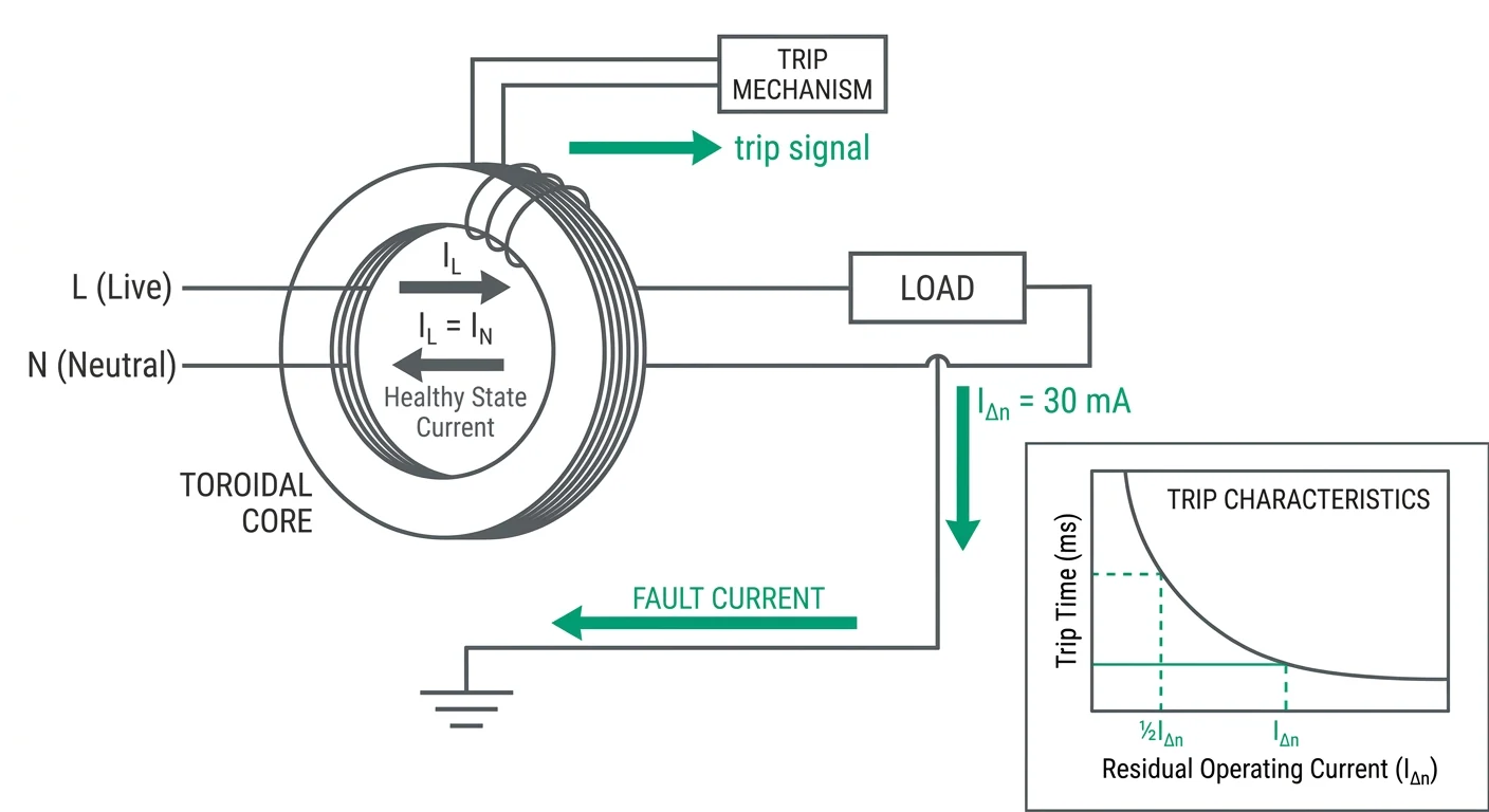
Every RCBO carries two independent sensing chains behind one trip latch. The overcurrent chain is the familiar bimetal and solenoid pair inherited from an MCB; the residual-current chain starts at a toroidal core through which both the line and the neutral conductor of the protected circuit pass. Under normal conditions the instantaneous currents in L and N are equal and opposite, so their magnetic fluxes cancel and the core carries no net flux. The sensing element monitors the vector sum IL + IN, which is nominally zero — it is not measuring the absolute current in either conductor.
When a residual current appears, the flux balance is broken and the core couples a small alternating voltage into a secondary winding. That signal is conditioned and compared against the detection threshold; on a sustained or fast-rising residual current the trip relay releases the latch and the main contacts open. Because the threshold sits between 0.5 IΔn and IΔn, and because the trip time is a function of the residual current magnitude rather than a fixed figure, the device behaves as an envelope rather than a single set point. IEC 61009-1 defines the limits of that envelope for both Type AC and Type A devices, and a compliant device must operate no slower than the values below.
| Applied residual current | Maximum trip time | Notes |
|---|---|---|
| 0.5 IΔn | No tripping | The device must remain closed; standing leakage below this value is not a device fault |
| IΔn | 300 ms | At the rated residual operating current the device must trip |
| 2 IΔn | 150 ms | Behaviour in the range where most genuine earth faults sit |
| 5 IΔn | 40 ms | Direct-contact and near-bolted leakage faults; the fastest requirement in the standard |
Type AC, Type A and Type B sensing elements
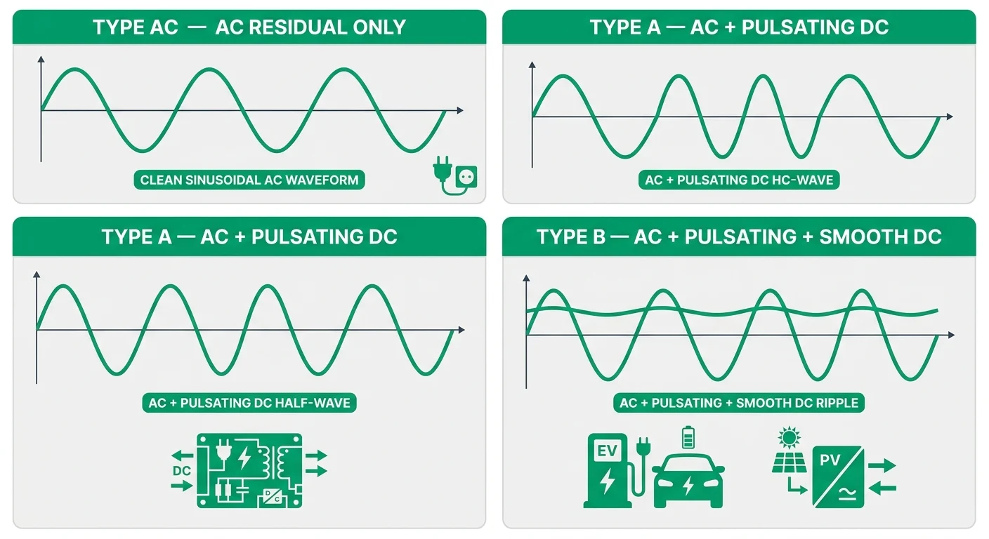
- Type AC responds to alternating sinusoidal residual currents only. It is the baseline sensing element and is adequate where the load is purely AC and free of electronic conversion — simple resistive and inductive final circuits, for example.
- Type A responds to alternating sinusoidal residual currents and to pulsating DC residual currents of either polarity, and must not be impaired by smooth DC residual current up to 6 mA. It remains the default choice for circuits fed from single-phase electronic equipment, since pulsating DC components can desensitise a Type AC core without the user ever seeing a trip.
- Type B responds to alternating, pulsating DC and smooth DC residual currents, and is specified where a smooth DC fault current above 6 mA is possible — three-phase rectifiers, variable-speed drives, some EV charging equipment and PV inverters. Type B devices are covered by IEC 62423 in addition to IEC 61009-1.
- The physical toroid is similar across the three; what changes is the sensing and evaluation circuit around it, which is why a Type A or Type B device cannot be substituted by a Type AC unit of the same IΔn and frame size. Match the type to the load, not just to the residual current rating.
The Most Common Causes of RCBO Tripping, Ranked by Frequency
The eight causes in the table below account for the large majority of RCBO tripping on domestic and light-commercial final circuits to IEC 61009-1 and, in Australia and New Zealand, AS/NZS 61009.1. The ranking reflects how often each cause is confirmed at the point of diagnosis — not how serious it is. A shared neutral and a genuinely defective device are both rarer than accumulated leakage, yet both are routinely misdiagnosed because their symptoms overlap with more common faults. The order shifts with the installation: on new-build housing with dense LED lighting and switch-mode power supplies, accumulated leakage dominates; on outdoor, agricultural, pool and EV circuits, moisture ingress and damaged insulation move straight to the top. Use the signature behaviour to form a hypothesis, then apply the confirming test in the right-hand column before you touch a termination.
| Rank | Cause | Signature behaviour | Test that confirms it |
|---|---|---|---|
| 1 | Accumulated leakage from SMPS and LED drivers | Trips at random, most often at switch-on or when the lighting or IT load is added; resets and holds for minutes to hours; several electronic loads share one device | Half-rated residual current test (0.5 × IΔn) at the device with all loads connected, or clamp the outgoing line and neutral together and read standing leakage with loads energised |
| 2 | Moisture ingress | Wet-weather or seasonal tripping; resets after the enclosure or fitting dries out; outdoor socket, garden lighting, irrigation and pool circuits affected first | 500 V DC insulation resistance test, line-to-earth and neutral-to-earth, on the isolated circuit; compare against the 1 MΩ minimum required by IEC 60364-6 verification and AS/NZS 3000 testing |
| 3 | Neutral-to-earth fault downstream | Holds with no load; trips only when load is drawn, or when a load on another circuit changes; can trip the RCBO's upstream device instead | Insulation resistance test between neutral and earth with the circuit isolated and the RCBO open; a clamp on the outgoing neutral with the circuit's own device open will show diverted current if the fault is downstream of another protective device |
| 4 | Damaged cable insulation | Intermittent tripping tied to a physical event — a door closing, a floorboard, rodent activity, buried cable movement — rather than to load | Split the circuit at its midpoint and insulation-resistance test line-to-earth and neutral-to-earth on each half separately; repeat until the low-resistance section is isolated |
| 5 | Shared or borrowed neutral | Trips as soon as the RCBO is closed even with no load on that circuit, or trips whenever the other circuit's load operates; two-way lighting and retrofitted second RCBOs are typical | Open every device, energise one at a time and record which combinations cross-trip; clamp the outgoing neutral with this RCBO open while the other circuit is loaded |
| 6 | Motor start leakage | Trips only during start-up or acceleration, then holds at running speed; correlated with motor cable length and with EMC filter configuration on variable-speed drives | Measure leakage with a clamp at the moment of start versus steady state; confirm the drive's filter leakage specification and the manufacturer's permitted motor cable length |
| 7 | DC residual current from EV or PV inverters | A Type AC or Type A device trips unpredictably during charging or generation, or holds through a real earth fault because smooth DC has desensitised its sensing core | Confirm the device type against the application: where smooth DC residual current above 6 mA is possible, IEC 62423 Type B or a residual direct current detecting device to IEC 62955 is required; verify the architecture in the documentation if no DC-capable leakage clamp is available |
| 8 | Genuinely defective device | Trips with the outgoing conductors disconnected and no load applied; fails to trip on the integral test button; shows heat damage, moisture staining or mechanical damage after a flood or a nearby surge | Disconnect the outgoing conductors, then operate the integral test button, which IEC 61009-1 requires to trip the device; confirm with a disconnection test from a test instrument to IEC 61557-6. If it trips with nothing connected, replace it |
Read the table as a decision ladder, not a menu. Distributed causes and single-point causes separate on one observation: if the RCBO holds with all loads disconnected, the fault lies in the wiring or in the device itself; if it holds with loads off but trips progressively as they are switched on, the cause is accumulated leakage or another load-related effect. Note also that two of these causes are not faults to be hunted at all — a shared neutral is a wiring error, and a DC residual current problem is a device-selection error. Both are corrected at the consumer unit or at the specification stage, not in the circuit. Establishing which of the three categories you are in before testing saves the most time in the field.
- Circuit type: outdoor, agricultural, bathroom, pool and EV circuits fail on insulation resistance far more often than dry indoor final circuits, which pushes moisture and cable damage up the ranking.
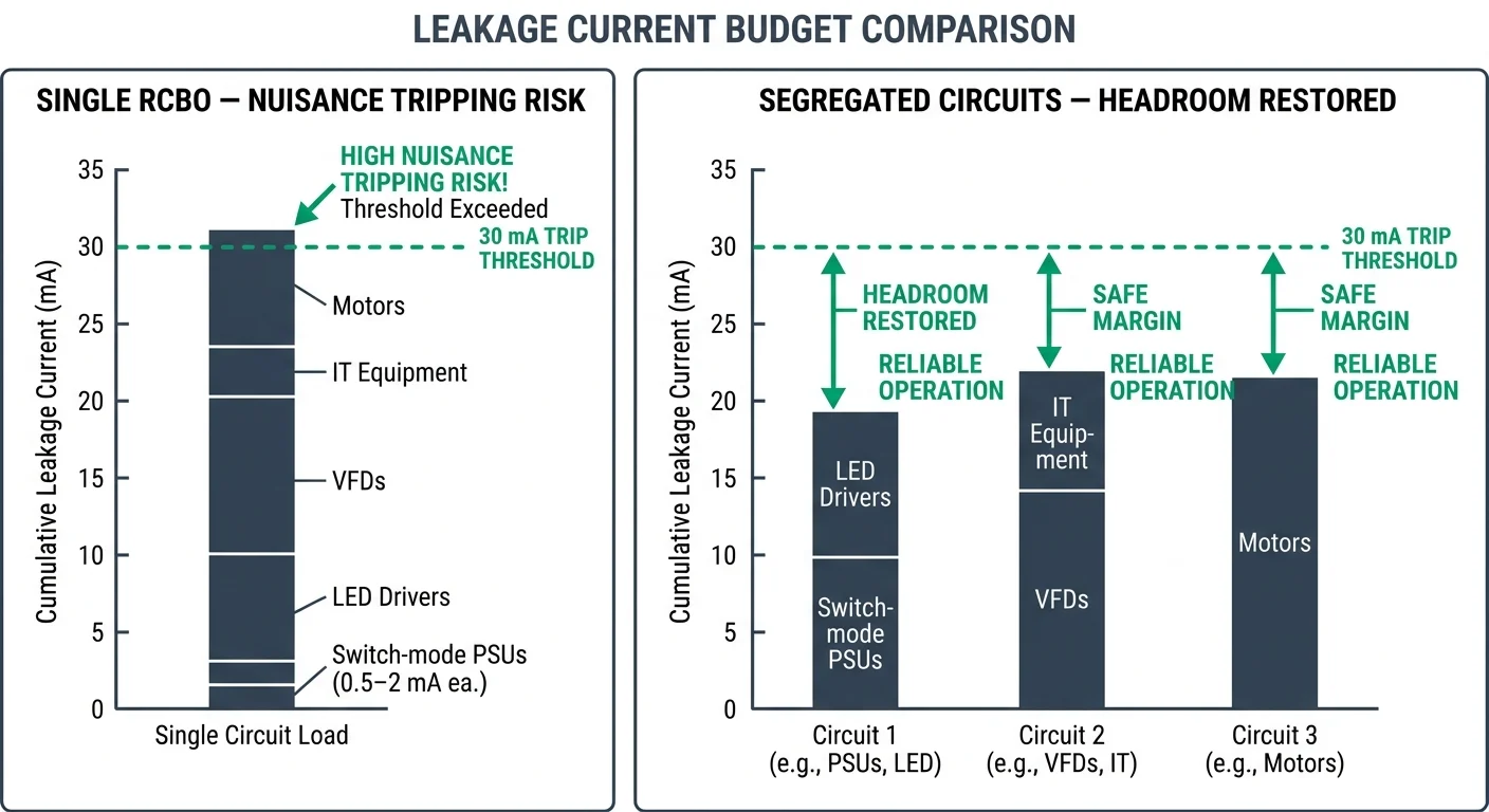
- Load profile: dense LED lighting, IT racks, multiple switch-mode supplies and long cable runs accumulate standing leakage that can sit close to the device's rated residual current before any fault exists.
- Installation history: circuits extended onto an existing ring, or a second RCBO retrofitted into an older consumer unit, are the usual origin of shared-neutral faults.
- Fault history: a device that has cleared a high-current short circuit, or survived a nearby lightning surge, may trip with no load afterwards — the integral test button then becomes the first check, not the last.
- Device type: Type AC, Type A and Type B behave differently under the same fault current, so tripping behaviour and compliance both change with the type fitted. Confirm the type marked on the device before interpreting any trip.
Nuisance Trips vs Real Faults: Reading the Pattern
The conditions surrounding a trip carry more diagnostic information than the trip itself. Timing, the state of the load, and how readily the device resets narrow the cause to one of a handful of mechanisms, and each mechanism has a different correct response. Pattern recognition gets you to the right test quickly, but it does not replace measurement: insulation resistance and leakage current readings are what confirm the diagnosis. The four patterns below cover the large majority of field cases.
Two cautions apply to the whole exercise. The test button verifies the trip mechanism and the internal test loop only; it says nothing about the wiring downstream or about actual residual current in the installation. And more than one mechanism can be present at once: a circuit with marginal standing leakage plus a switching transient will produce a pattern that fits no single category above, which is why the first measurement after any unexplained trip should be leakage current, not a replacement device.
Field Tests: IR Test, Ramp Test, Trip-Time Check and the Leakage Budget
The order of these tests matters more than the tests themselves. Insulation resistance comes first because a genuine L–PE or N–PE fault will distort every residual-current measurement taken afterwards — a ramp test on a circuit with 0.2 MΩ to earth simply confirms the tripping you already have. Work down the sequence, stop when a step fails, repair, and start again from the top. A working RCBO is not proof that the circuit is sound, and a sound circuit is not proof that the RCBO is within tolerance; both are checked separately.
- Isolate and disconnect — lock off, prove dead, then remove the outgoing line and neutral from the RCBO so that parallel loads, borrowed neutrals and the device's own internal electronics cannot mask the reading.
- Insulation resistance — test L–N, L–PE and N–PE at the voltage given in the table below, with all loads and lamps removed and all switches in the on position.
- No-load energise — reconnect the device, energise with the outgoing circuit still unloaded. A trip with nothing connected points to wiring topology (shared neutral, N–PE inversion, parallel earth path) rather than to load leakage.
- Ramp test — raise the residual current slowly and record the value at which the device operates. This returns the actual IΔn of the unit, not the nameplate value.
- Trip-time check — test at ½IΔn (must not trip) and at IΔn, then at 2IΔn and 5IΔn if the instrument offers them.
- Load restoration and leakage audit — bring loads back one at a time with a mA-resolution leakage clamp and record where the standing residual current accumulates.
| Test | Applied between | Test voltage | Acceptable result | What it tells you |
|---|---|---|---|---|
| L–N | Line and neutral of the isolated circuit, loads removed | 500 V DC | ≥ 1 MΩ; healthy new cable normally reads far higher | A low reading is a cable or accessory insulation failure. It has nothing to do with the RCBO. |
| L–PE | Line and protective earth | 500 V DC | ≥ 1 MΩ | The classic earth-leakage fault. Localise by splitting the circuit at accessories. |
| N–PE | Neutral and protective earth | 500 V DC | ≥ 1 MΩ | Produces faults that appear only under load, and is a frequent cause of intermittent tripping that is wrongly blamed on the device. |
The test button only proves that the trip mechanism releases; it says nothing about the residual operating current, and it does not discriminate between a Type A and a Type AC device. The ramp test does. Operate it with the outgoing circuit connected and energised under normal load, raise the residual current gradually, and note the value at which the device opens. Under IEC 61009-1 the device must operate between 0.5 IΔn and IΔn — so a 30 mA unit should trip somewhere in the 15–30 mA band. Reading below 0.5 IΔn indicates a device that is drifting low and will nuisance-trip; a device that holds past IΔn has failed and must be replaced, not adjusted.
| Applied residual current | IEC 61009-1 limit | Expected result | Reading this means |
|---|---|---|---|
| ½ IΔn (15 mA on a 30 mA device) | No trip | Device holds, observed for at least 2 s | A trip here is a nuisance-trip characteristic — check instrument accuracy, then replace the device. |
| IΔn (30 mA) | ≤ 300 ms | Trips | No trip at IΔn is a failed device, irrespective of age. |
| 2 IΔn | ≤ 150 ms | Trips | Confirms the sensing circuit responds at realistic fault currents. |
| 5 IΔn | ≤ 40 ms | Trips | Verifies fast disconnection for indirect contact protection. |
| Ramp (0 to IΔn) | Operate between 0.5 IΔn and IΔn | Records actual operating current | Low readings explain recurring trips; high readings explain failure to protect. |
With the circuit proven sound and the device within tolerance, the remaining question is how much residual current the installation is legitimately producing before any fault exists. Measure it as a standing figure, with all normal loads running, not as a single appliance reading. A leakage clamp with mA resolution and true RMS response, closed around the line and neutral conductors together at the outgoing side of the RCBO, reads the residual current directly; switch off each final circuit and each appliance in turn and record the drop, which is that item's contribution. For circuits feeding rectifier loads — IT equipment, LED drivers, single-phase drives — check the smooth DC component as well, because a sustained DC residual current above a few milliamps can desensitise a Type A device that was correctly selected for AC and pulsating DC faults.
| Load type | Why it leaks | Behaviour on the clamp | Action if it dominates |
|---|---|---|---|
| IT equipment, monitors, switch-mode supplies | Y-capacitors bridge line and earth in every PSU | 0.25–1.5 mA per unit, cumulative across a ring final | Split the final circuit or move part of the load to a separately protected way. |
| LED drivers and electronic lighting | Earth-referenced filter components; leakage varies with dimming level | Rises sharply when dimmed or at end of life | Test with drivers disconnected; replace failed drivers rather than the RCBO. |
| Variable-speed drives with EMC filters | Filter capacitance discharges to earth; rises with motor cable length | Tens of milliamps on long motor runs | Check manufacturer data, shorten motor cable or select a drive variant with a lower earth leakage current. |
| Water heating, cookers, outside sockets | Moisture ingress and ageing element insulation | Increases with damp and after rainfall | Insulation resistance retest of the appliance; a genuine fault, not nuisance leakage. |
| Rectifier or DC-containing loads on a Type A device | Smooth DC residual current can blind the sensing circuit | Low AC reading despite tripping | Confirm the correct device type is installed; a Type B device may be required for the load. |
Fixes That Work: Segregation, Wiring and Correct Device Selection
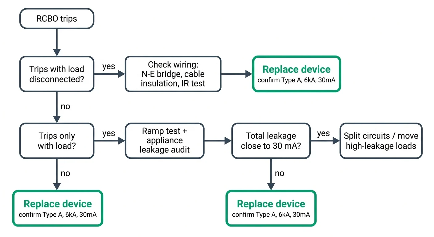
Once you've identified the cause of tripping — whether it's cumulative leakage, a damaged cable, or a specific appliance — the fix must address the root cause, not mask it. The sequence below follows increasing cost and disruption: start with the simplest wiring corrections, then move to circuit segregation, and only replace the device if the fault cannot be resolved at the installation level. Each step assumes you've confirmed there is no immediate shock risk; if insulation resistance is below 1 MΩ to earth or you detect a hard fault, isolate and repair that circuit before proceeding.
Fix Sequence: From Simplest to Most Invasive
- Correct any N-E bridge or swap: Check that neutral is not bonded to earth downstream of the RCBO, and that the load-side neutral from the RCBO returns only to its own protected circuit. A single crossed neutral will trip multiple devices.
- Split circuits across multiple RCBOs: If total leakage exceeds 30% of rated IΔn (typically 9 mA for a 30 mA device), divide the load. A 10-way sub-board with individual 30 mA RCBOs will tolerate ten times the leakage of a single upstream 30 mA RCD.
- Move high-leakage loads to dedicated protection: IT equipment, variable-speed drives, and medical devices with class-I metal enclosures may each leak 3–5 mA. Route these through a separate RCBO or a 100 mA time-delayed upstream device where code permits.
- Add a dedicated circuit for the offending load: If a specific appliance causes nuisance trips under inrush or motor start, install a dedicated RCBO with appropriate discrimination. Type A devices are required for any load with rectified DC components per IEC 61009-1 Annex A.
- Re-terminate or replace damaged cables: If insulation resistance is marginal (1–10 MΩ) and localized to one run, pull new cable or re-terminate at both ends. Do not rely on an RCBO to mask a cable fault indefinitely.
- Replace the device only if selection was incorrect: If the existing RCBO is Type AC and the load contains inverter or SMPS circuits, replace with Type A or Type B as required. If the rated In is too low for inrush or the curve is wrong for the load, uprate or change the curve — but do not increase IΔn beyond what the installation's earthing system and shock-risk assessment allow.
TPKELE supplies IEC 61009-1 Type A and Type AC RCBOs from 6 A to 63 A, 30 mA and 100 mA, with C and B curves. All devices are tested to Annex B and ship with calibration certificates.
Selecting a Replacement RCBO Without Repeating the Fault
Replacing a tripping RCBO is a specification exercise, not a like-for-like swap. The most common reason a new device trips on the same circuit is that the replacement was chosen by rated current alone, while pole configuration, residual-current type, breaking capacity or the neutral terminal layout quietly differed from the device it replaced. Before ordering, confirm every parameter below against the removed device's marking, the circuit's measured leakage and the fault level at the board. Where a datasheet does not state a value explicitly, treat it as requiring confirmation from the manufacturer for that exact catalogue number.
The residual-current type is the parameter most often carried over incorrectly. A Type AC device responds only to sinusoidal residual currents, while a Type A device also responds to pulsating DC residual currents such as those produced by single-phase rectifier inputs in LED drivers, electronic power supplies, single-phase EV chargers and inverter-fed equipment. Where such loads exist — as they do in most modern final circuits — a straight Type AC replacement reproduces the original trip pattern. Type B (covered by IEC 62423) additionally detects smooth DC residual currents and is normally an application-specific choice for three-phase rectifiers, PV inverters and DC-capable charging equipment; it should not be selected by default.
On sensitivity, the rule is simple: IΔn is a protection level, not a tolerance setting. 30 mA is the value on which additional protection against electric shock under IEC 60364-4-41 depends, and 100 mA or 300 mA devices are intended for fire protection or selective coordination further upstream. Fitting a 300 mA RCBO in place of a tripping 30 mA device does not remove the earth leakage — it removes the evidence, leaves the fault in service, and takes the circuit outside the shock-protection requirements it was designed to meet. The measured leakage budget and the trip pattern established by the field tests should decide whether the fault is cleared, the load is split, or the circuit is redesigned. For replacement devices matched to the circuit rather than to the old part number, the RCBO range sets out type, IΔn and breaking capacity per catalogue number, and we can confirm certification documents against a specific market on request via contact.
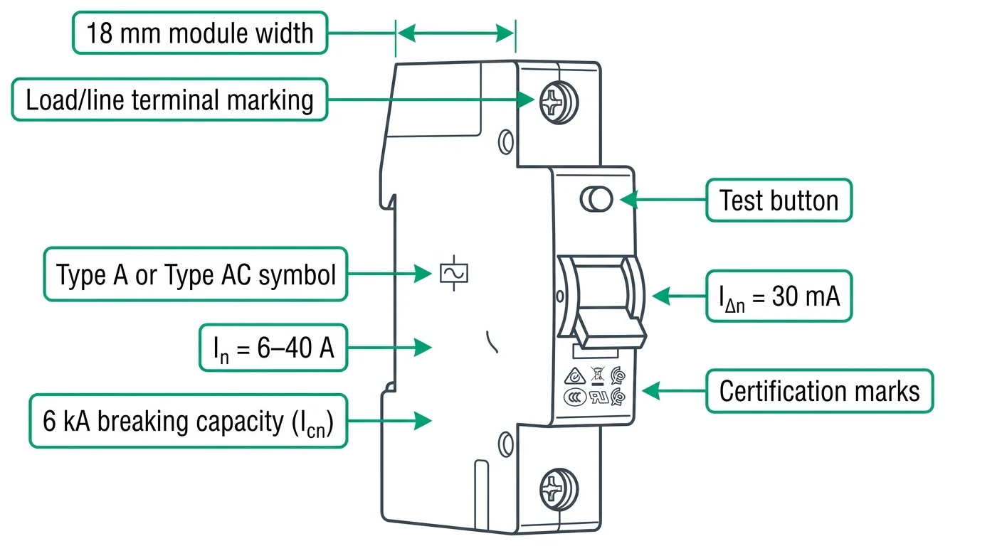
Replacing the RCBO: Specs to Confirm Before You Order
By this point you have either cleared the fault or confirmed the device itself is the problem — the ramp test drifted, the trip time fell outside the envelope, or the mechanism will not reseat after a genuine earth fault has been removed. Ordering the replacement is a matching exercise, not a shopping one. A device that looks identical on the front can differ in residual-current type, rated current, breaking capacity or neutral configuration, and any one of those mismatches either invalidates the circuit's protection or fails an inspection. Work through the checklist below against the failed device's own label and the original datasheet, not against a photograph.
Before placing the order, confirm that the underlying cause has actually been addressed. A replacement fitted onto an uncleared insulation fault or an overloaded circuit will trip in exactly the same pattern, and the second failure is often attributed to the new device rather than the circuit. Note the readings you took during testing — insulation resistance, ramp-test operating current, trip times at IΔn and 5IΔn — so the replacement can be compared against a baseline. For boards with several RCBOs, it is worth replacing a failed unit with the same reference as its neighbours so that discrimination and spare-part stock stay consistent.
Product detail
TPKELE 1P+N 18 mm RCBO
Full type, rated current, sensitivity, breaking capacity, trip characteristic and certification detail for the 1P+N 18 mm range is listed on the product page. Use it to match a failed device spec-for-spec, or send the label details to our technical team for a direct cross-reference.