What an RCBO Actually Does (and Why It Replaces MCB + RCCB)
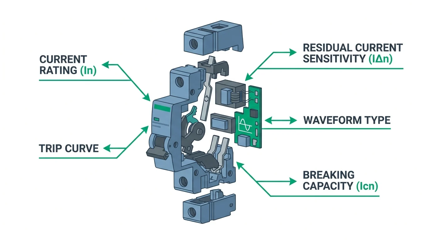
An RCBO — residual current circuit breaker with integral overcurrent protection — combines two protection mechanisms in a single DIN-rail device. It trips on both overload and short-circuit conditions (the MCB function, governed by IEC 60898-1 characteristics) and on residual current imbalance (the RCCB function, per IEC 61009-1). When insulation fails or a person contacts a live conductor, fault current returns through earth rather than the neutral; the RCBO's differential transformer detects this imbalance and opens the circuit within milliseconds. The device occupies one module width per protected pole, saving panel space and eliminating the need to coordinate separate upstream RCCBs with downstream MCBs.
Protection Functions in One Device
- Overload protection: thermal element trips on sustained current above rating (e.g. 16 A RCBO opens at 1.13–1.45 × In per IEC 61009-1 Table 6).
- Short-circuit protection: magnetic release trips instantaneously when fault current exceeds the curve threshold (B-curve: 3–5 × In; C-curve: 5–10 × In).
- Residual current protection: differential transformer monitors phase and neutral currents; any imbalance ≥ rated IΔn (typically 10, 30 or 300 mA) trips the mechanism within the time specified by the Type (AC, A, B or F).
When to Specify an RCBO
Choose an RCBO when the final circuit demands both overcurrent and earth-fault protection in a single point of isolation, or when mixed residual-current sensitivities make a shared upstream RCCB impractical. Typical applications include socket outlets in wet locations (30 mA Type A per IEC 60364-4-41), EV charge points (Type B for DC fault detection), and circuits feeding variable-speed drives or switch-mode power supplies that inject DC residual current. In contrast, a shared RCCB remains cost-effective for a group of lighting circuits with negligible leakage and uniform sensitivity requirements, where individual RCBOs would offer no selectivity advantage.
Step 1: Sizing the Current Rating (In)
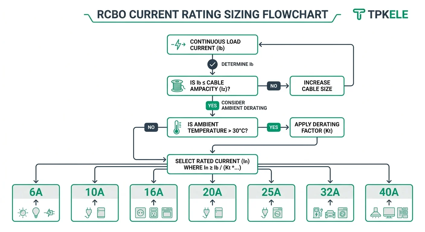
The rated current (In) of an RCBO is the maximum continuous current the device can carry without tripping on overload. Under IEC 61009-1, standard In values run 6, 10, 16, 20, 25, 32, 40, 50 and 63 A. Selecting the right value is a two-step process: first establish the continuous design current of the circuit (Ib), then verify the cable's current-carrying capacity (Iz) after all derating factors are applied. The RCBO must satisfy Ib ≤ In ≤ Iz — a device undersized for the load nuisance-trips; one oversized for the cable leaves the conductors unprotected.
Design current (Ib) is calculated from the connected load. For resistive loads divide the load wattage by the supply voltage; for motor circuits apply a demand factor and account for starting current per IEC 60947-4-1 or the relevant motor standard. Once Ib is known, move to the cable side: look up the cable's tabulated current-carrying capacity from IEC 60364-5-52 (or AS/NZS 3008.1 for Australian projects) for the chosen installation method, then multiply by all applicable derating factors — grouping, ambient temperature, and thermal insulation. The result is the derated Iz that bounds your In choice from above.
Step 2: Pole Configuration — 1P+N, 2P, 3P, 4P
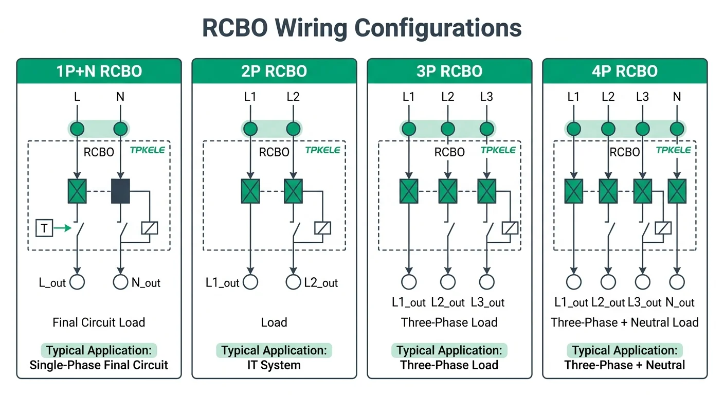
Pole count determines which conductors an RCBO monitors for residual current and physically interrupts on fault or overload. IEC 61009-1 defines four standard configurations, each suited to a different circuit topology. Selecting the wrong pole count is not merely a wiring inconvenience — an RCBO that does not switch the neutral leaves a shock hazard on circuits where the neutral can become live under fault conditions, and one that monitors the wrong conductor set will miss leakage current entirely.
Step 3: Trip Curves B, C and D
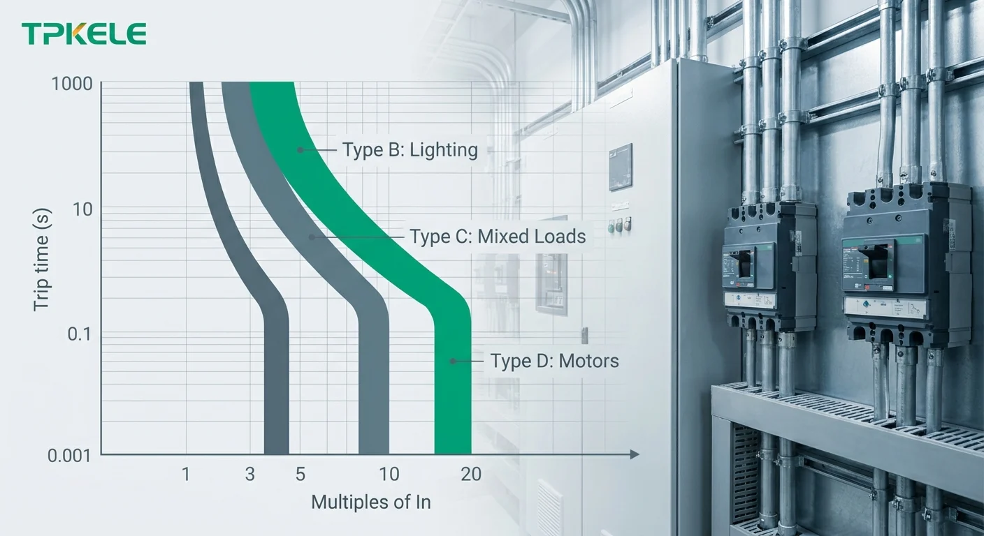
The trip curve determines when the magnetic release operates during overload and short-circuit events. IEC 61009-1 defines three standard curves—B, C, and D—each with a distinct instantaneous trip range expressed as multiples of rated current (In). Curve B trips between 3–5× In, Curve C between 5–10× In, and Curve D between 10–20× In. Selection depends on the inrush profile of the connected load: resistive circuits tolerate tighter bands, while inductive equipment requires headroom to ride through start-up transients without nuisance tripping.
| Curve | Magnetic Trip Range | Typical Application | Load Characteristic |
|---|---|---|---|
| B | 3–5× I<sub>n</sub> | Lighting circuits, domestic sockets, resistive heating | Low or no inrush; fast protection desirable |
| C | 5–10× I<sub>n</sub> | Mixed commercial loads, small motors, general distribution | Moderate inrush; most common curve in panel building |
| D | 10–20× I<sub>n</sub> | Transformers, large motors, welding equipment, X-ray machines | High inrush current that decays within 10–20 ms |
Curve C accounts for approximately 70–80 % of installed RCBOs in commercial and light-industrial panels because it balances protection speed with tolerance for capacitive or small-motor loads. Curve B is reserved for purely resistive or electronic loads where faster clearing reduces let-through energy. Curve D is specified when commissioning records or nameplate data confirm starting currents exceed 10× rated—using it elsewhere sacrifices discrimination and raises arc-flash incident energy. In three-phase installations, verify that the curve applies to every pole; some older or non-compliant devices apply the magnetic threshold only to line poles, leaving the neutral unprotected during single-phase faults.
Instantaneous trip thresholds are factory-set and non-adjustable in standard DIN-rail RCBOs. If a load exhibits documented inrush that falls between two curve bands—common with variable-frequency drives or soft-start contactors—move to the next higher curve rather than over-sizing the current rating. Over-sizing In undermines cable protection and violates coordination with upstream devices. For installations subject to AS/NZS 3000 or IEC 60364-4-41, verify that the selected curve maintains fault-loop impedance low enough to guarantee disconnection within 0.4 s (TN systems) or 5 s (TT systems) at the maximum prospective fault current for the site.
Step 4: Residual Current Sensitivity (IΔn) — 10, 30, 100, 300 mA
Residual current sensitivity (IΔn) defines the fault current at which the RCBO must trip. IEC 61009-1 specifies that a device shall trip within the time limits when the residual current reaches its rated IΔn, and shall not trip on residual currents up to 0.5 × IΔn. The four standardised values — 10, 30, 100 and 300 mA — are not interchangeable: each addresses a distinct protection objective, and selecting the wrong sensitivity either leaves a hazard unmitigated or produces nuisance tripping that undermines circuit reliability.
When building a selective scheme, the sensitivity ratio between adjacent tiers should be at least 3:1 (e.g., 100 mA upstream, 30 mA downstream), and the upstream device should carry a time delay (S-type per IEC 61009-1 Annex B) or a short-time withstand rating sufficient to allow the downstream device to clear first. A plain 100 mA RCBO without time-delay will not reliably discriminate against a 30 mA device under all fault conditions — verify the time-current characteristic curves for the specific devices being paired.
Step 5: Waveform Type — AC, A, F, B
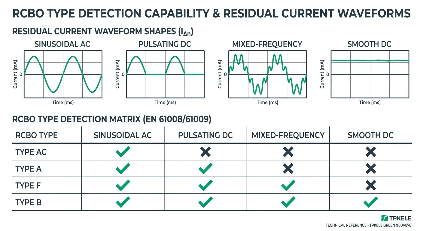
Residual current protection was originally designed to detect sinusoidal AC fault currents. Modern loads — variable speed drives, LED drivers, switch-mode power supplies — produce pulsating DC or high-frequency leakage that Type AC devices may not reliably trip on. IEC 61009-1 defines four waveform types, each capable of detecting progressively broader fault signatures. Specifying the correct type ensures the RCBO responds to the actual fault current your circuit will produce, not just the legacy 50 Hz sine wave.
| Type | Detects | Typical Application |
|---|---|---|
| AC | Sinusoidal AC residual current only | Purely resistive loads: incandescent lighting, resistive heaters, non-electronic circuits |
| A | AC + pulsating DC up to 6 mA smooth component | General socket circuits, household appliances, single-phase motor drives, LED lighting, IT equipment |
| F | AC + A + mixed frequencies up to 1 kHz | Variable frequency drives, photovoltaic inverters, UPS systems, large motor controls |
| B | AC + A + F + smooth DC, frequencies up to 20 kHz | EV charging stations, three-phase rectifiers, medical equipment, industrial inverter loads |
The distinction matters because pulsating DC — produced by half-wave or full-wave rectifiers — can saturate the magnetic core of a Type AC device, preventing it from tripping even when residual current exceeds 30 mA. Type A devices incorporate core designs that tolerate up to 6 mA smooth DC while still sensing AC and pulsating DC faults. Type F extends sensitivity into the low-kilohertz range, capturing leakage from PWM inverters. Type B handles all waveforms including pure DC fault currents, required when battery-backed systems or DC-coupled circuits are present.
For panel builders, the practical rule is: specify Type A as the baseline for any circuit that may feed electronic equipment, Type F for circuits supplying frequency converters or solar inverters, and Type B for EV chargers or three-phase rectifier loads. Confirm waveform type requirements with local regulations and the manufacturer's datasheet; not all RCBO families offer Type F or B in every pole and current-rating combination.
Breaking Capacity, Standards and Panel-Builder Checklist
The final selection filter is the short-circuit breaking capacity (Icn), the governing product standard, and the physical and documentary requirements for installation. Icn must equal or exceed the prospective short-circuit current at the point of installation, which is driven by transformer kVA, impedance and cable length upstream. For most domestic and light commercial final circuits in Europe and Australia, 6kA is sufficient; sub-distribution close to the main board, or installations fed by larger transformers, typically require 10kA.
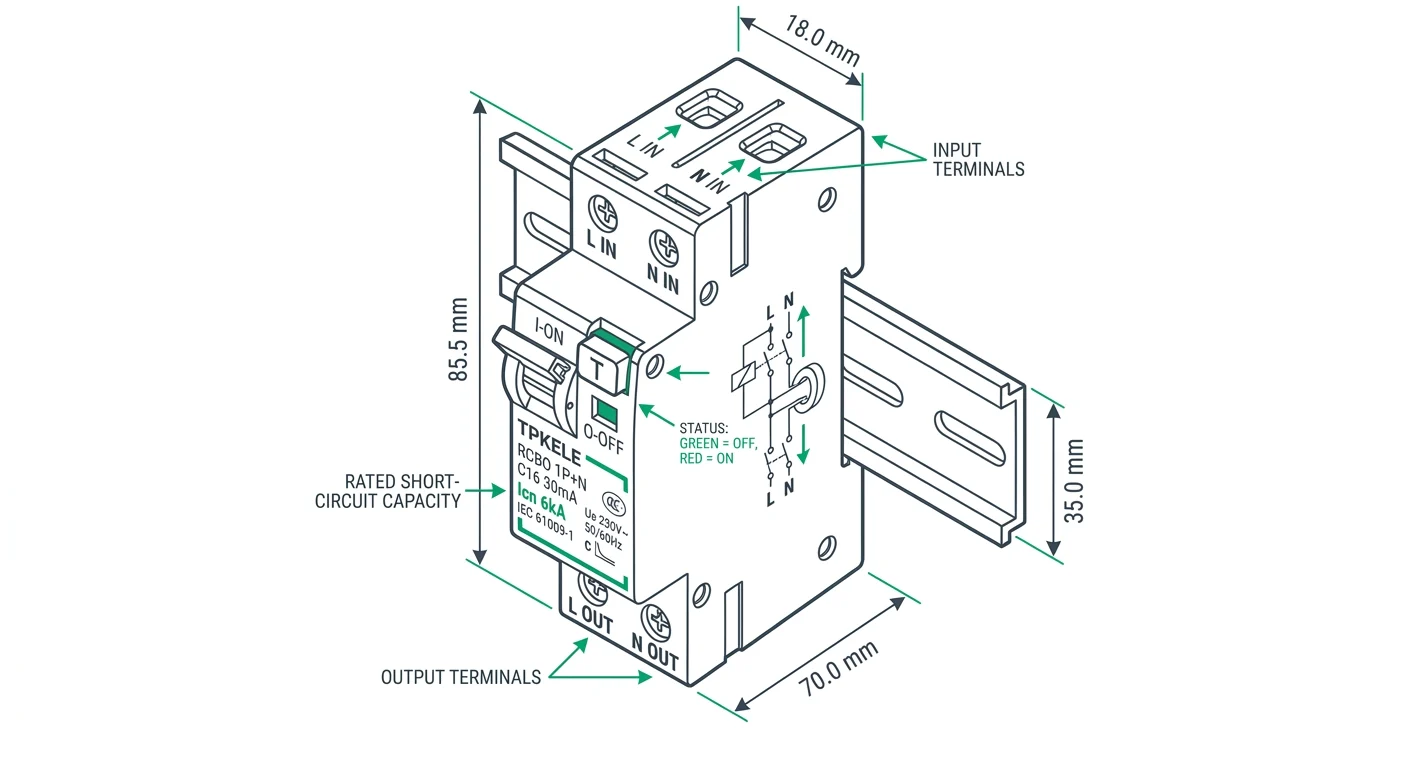
DIN-rail width matters when the consumer unit is already tight. A 1P+N RCBO is commonly built in an 18mm (1 module) or 36mm (2 module) frame depending on the construction — the compact single-module version saves space but may limit terminal capacity and auxiliary options. 2P, 3P and 4P devices scale accordingly at 36mm, 54mm and 72mm. Always confirm the exact module count against the enclosure's row capacity before finalising the single-line diagram.
Request compliance documents, dimensional drawings and type test summaries for the ratings used in your panel build.
Specify TPKELE RCBOs for Your Next Project
Once the five parameters are fixed, the specification collapses into one order line: device type, pole configuration, rated current, trip curve, residual current sensitivity, waveform type, breaking capacity and module width. For a final distribution circuit on a 230/240 V TN-S or TT system, that line typically reads RCBO, 1P+N, In 6 A, Curve C, IΔn 30 mA, Type A, 6 kA, 18 mm. Write it in that order in the bill of materials and on the panel schedule, so the device ordered, the device fitted and the device inspected are verifiably the same item. Where a catalogue lists several variants on one mechanical platform, the variant code — not the family name — is what determines Type A or Type AC behaviour and the IΔn value; confirm both against the datasheet for the exact model before releasing the BOM.
TPKELE's 1P+N 18 mm RCBO occupies a single DIN module and is intended for single-phase final circuits where an MCB plus a separate RCCB would consume two or more ways. It is designed against IEC 61009-1, with AS/NZS 61009.1 relevant to the Australian and New Zealand markets. Ratings, curves, sensitivity options and any third-party approval marks vary by variant, so treat those attributes as model-specific: request the current datasheet and, where the project requires it, the declaration of conformity before final selection. Tripping times, selectivity with upstream devices and neutral-switching behaviour should be read off that datasheet rather than assumed across the range.
RCBO series
1P+N 18 mm 6 kA Type A RCBO
Single-module RCBO for single-phase final circuits. Full ratings, trip curves, residual current sensitivities and approvals for each variant are listed on the product page and datasheet.
Send your panel schedule or a list of the variant codes you need — pole configuration, In, curve, IΔn, waveform type — and TPKELE will confirm the matching models, lead time and quotation. Datasheets for the specified variants and, on request, declarations of conformity are supplied with the quotation.