DC SPD Selection: Imax, Iimp, Uc and Type 1 vs Type 2
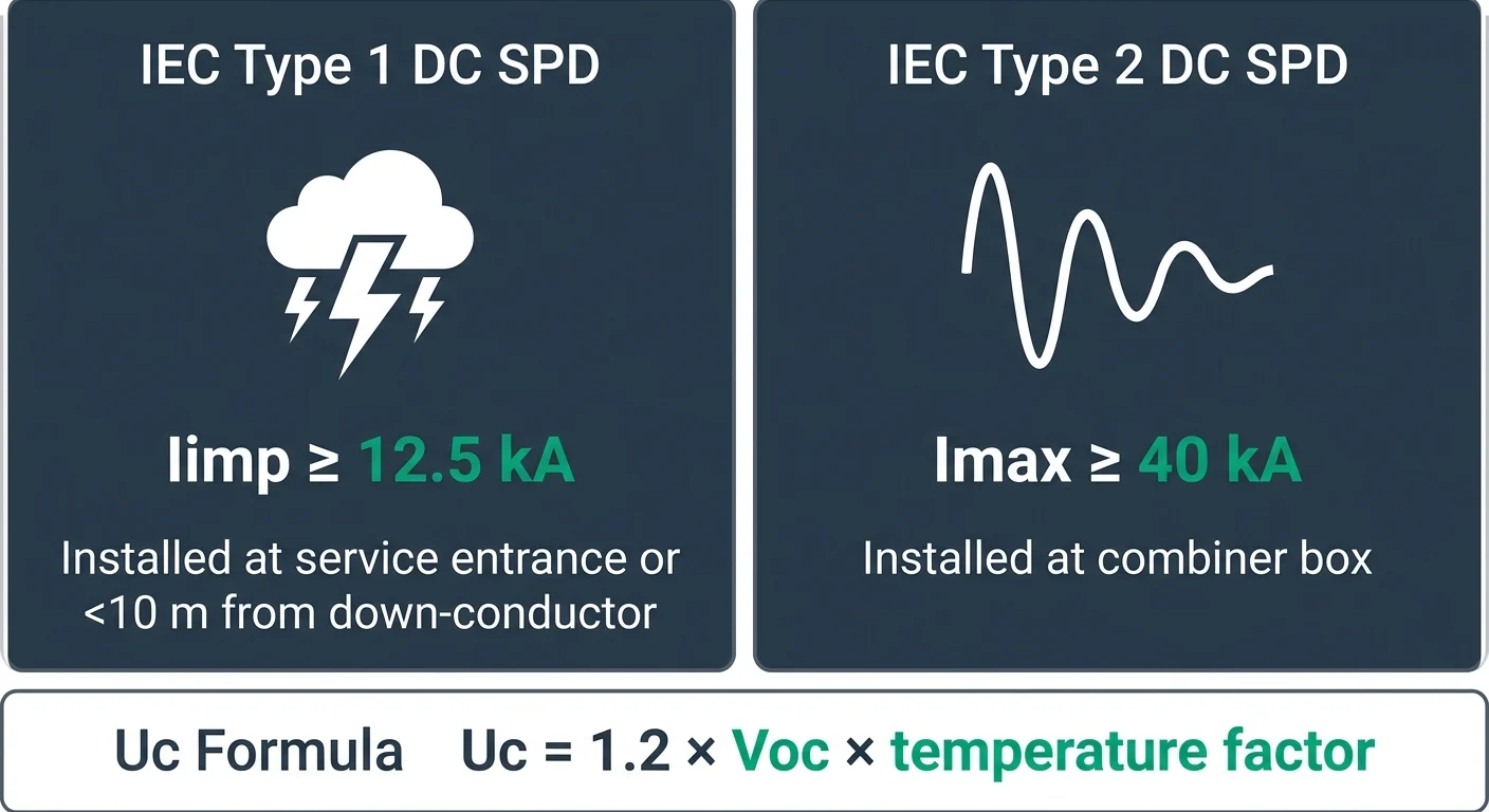
The DC surge protective device (SPD) is the single most important component inside a PV DC protection box. Its job is to clamp transient overvoltages from direct or nearby lightning strikes and divert the surge current to earth before it reaches the inverter DC input. Selection comes down to four parameters defined in IEC 61643-31: the SPD type (1, 2 or combined 1+2), the impulse current Iimp (10/350 µs), the nominal discharge current In and maximum discharge current Imax (8/20 µs), and the maximum continuous operating voltage Uc. Getting any one of these wrong will either leave the inverter exposed or cause the SPD to fail prematurely in service.
The decision between Type 1 and Type 2 is driven by lightning exposure and the location of the SPD relative to the array. Type 1 SPDs are specified when a direct strike onto an external Lightning Protection System (LPS) is possible and part of the lightning current can be conducted into the DC circuit, typically on buildings with an external LPS or on free-field arrays with masts. Type 2 SPDs handle induced surges only and are the default for rooftop systems without an LPS or at the inverter end of long DC runs. For most C&I and utility plants a Type 1+2 combined SPD near the array combined with a Type 2 at the inverter is now standard practice.
| Parameter | Type 1 (per IEC 61643-31) | Type 2 (per IEC 61643-31) | When to use |
|---|---|---|---|
| Impulse current Iimp (10/350 µs) | ≥ 12.5 kA per pole | Not required | Type 1: buildings with external LPS, free-field arrays exposed to direct strikes |
| Max discharge current Imax (8/20 µs) | Typically ≥ 25 kA | ≥ 40 kA per pole (common 40 kA / 60 kA) | Type 2: rooftop PV without LPS, inverter-side protection |
| Nominal discharge current In (8/20 µs) | ≥ 15 kA typical | ≥ 20 kA typical | Verify against separation distance and cable length |
| Voltage protection level Up | ≤ inverter DC Uw with margin | ≤ inverter DC Uw with margin | Must be below the inverter DC port withstand voltage |
| Max continuous DC voltage Uc | > 1.2 × Voc(STC) × k_T | > 1.2 × Voc(STC) × k_T | Both types; see warning below |
| Short-circuit withstand Iscpv | Must exceed array Isc at the SPD location | Must exceed array Isc at the SPD location | Required by IEC 61643-32 for PV applications |
DC MCB and String Fuse Sizing for PV Arrays
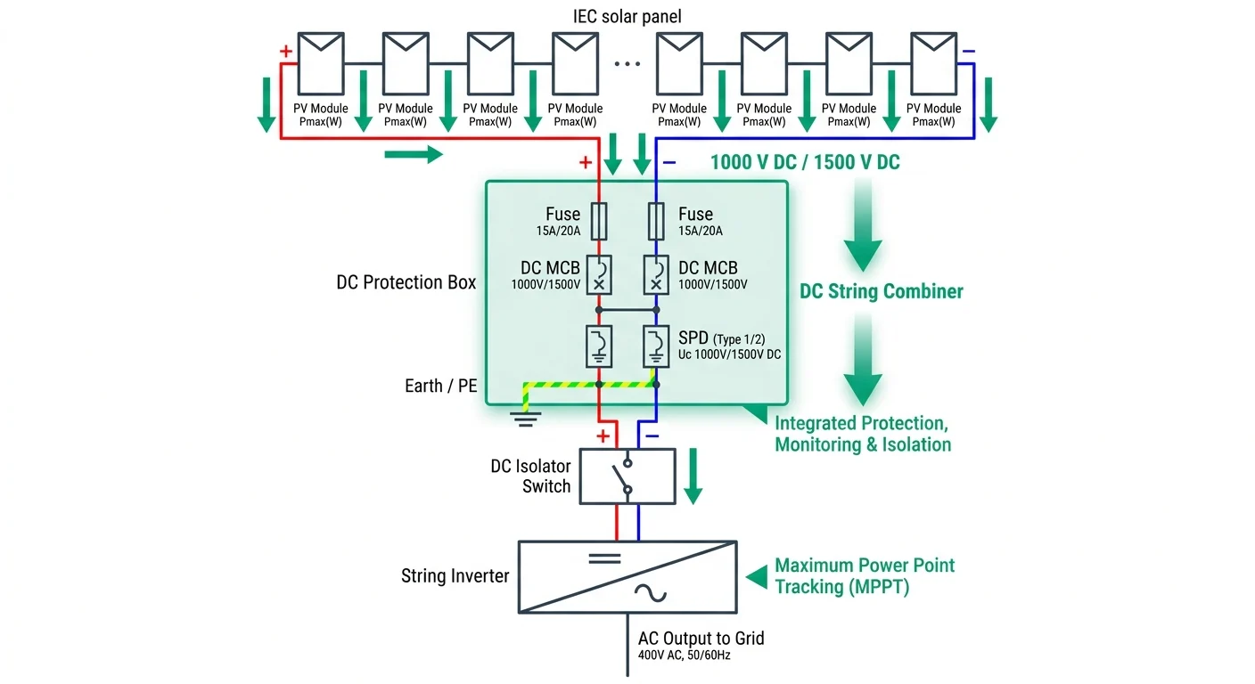
DC MCBs and string fuses form a coordinated protection strategy in PV systems, each addressing different fault scenarios. String fuses protect against individual string faults and reverse current, while DC MCBs isolate array strings and coordinate with downstream DC SPD and inverter protection. Correct pole count and tripping characteristic selection depends on your DC bus topology—grounded or floating—and short-circuit current magnitudes from parallel-connected strings.
DC Bus Topology and MCB Pole Configuration
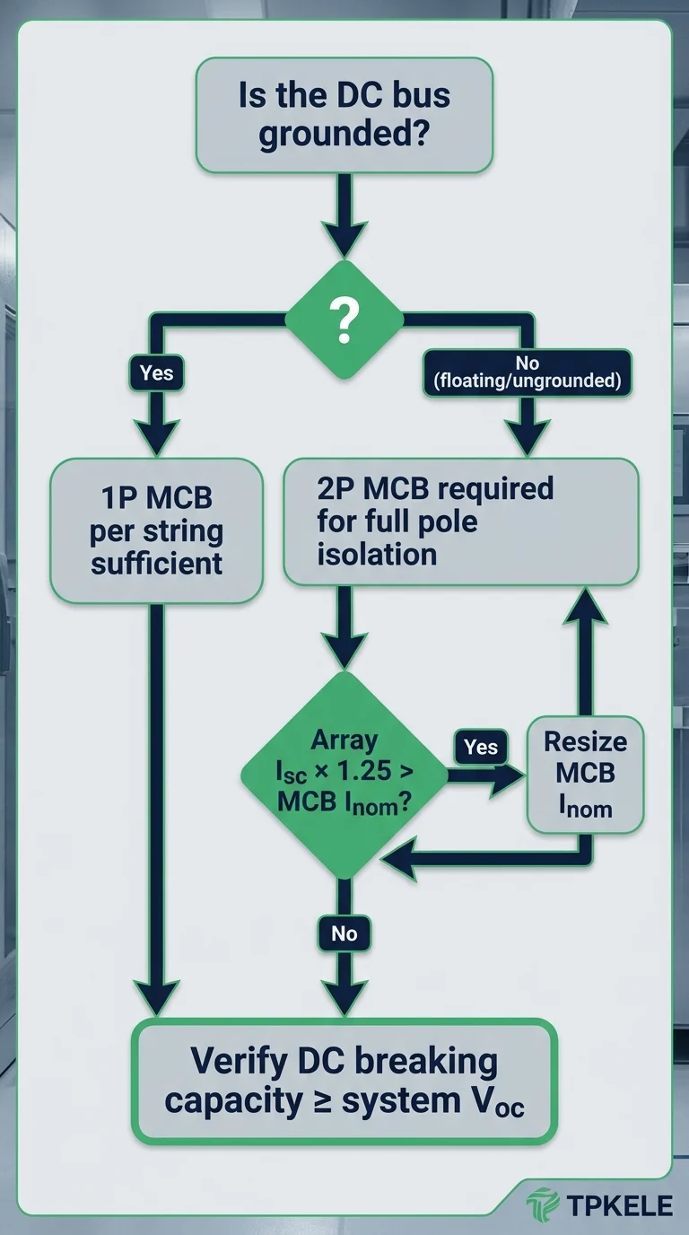
In ungrounded (floating) DC systems, both positive and negative conductors must be protected; a single ground fault may not immediately trip protection, so 2-pole MCBs are required to isolate the entire string circuit. In grounded systems (negative or positive conductor grounded through a low-impedance path), a single pole MCB on the ungrounded conductor can interrupt the fault loop, though local regulations and utility guidelines may mandate 2-pole protection regardless. Verify your regional standard—IEC 60364-7-712 recommends 2-pole for enhanced safety in most scenarios.
| Configuration | DC Bus Type | MCB Poles | String Fuse Requirement | Typical Application |
|---|---|---|---|---|
| 1P MCB + Neutral Ground | Grounded (negative to ground) | 1P protecting positive string | DC fuse per string (IEC 60269-6) | Small residential, code-permitted regions |
| 2P MCB + Floating Bus | Ungrounded (floating) | 2P protecting both positive and negative | DC fuse per string (IEC 60269-6) | Residential, C&I, utility-scale (recommended) |
| 2P MCB + Optional Ground | Grounded or hybrid | 2P for redundancy and safety | DC fuse per string (IEC 60269-6) | High-reliability systems, export markets |
Short-Circuit Current Coordination: I<sub>sc</sub>-String vs I<sub>nom</sub>
Each string generates a short-circuit current Isc-string (typically 110–130% of nameplate Isc) under fault conditions. When multiple strings are in parallel, the array combines these currents; this combined current must not exceed the DC MCB's rated breaking capacity (Icn). The string fuse rating (Inom) is selected to protect individual strings: for a string Isc of 12 A, a 16 A fuse is typical (per IEC 60269-6); the MCB protecting all strings must tolerate the sum of parallel string faults. Always size DC MCB breaking capacity ≥ array Isc + 25% margin.
Tripping Characteristic (B, C, D Curves) for DC PV Circuits
DC MCBs use tripping curves (instantaneous magnetic thresholds) calibrated for DC fault speed and load inrush. Type B MCBs trip at 3–5× rated current and are suitable for sensitive electronics and low-impedance circuits. Type C (5–10× rated current) suit standard PV arrays and mixed AC/DC circuits. Type D (10–20× rated current) accommodate high inrush or heavy cable runs. For PV DC circuits, Type C is standard; Type D may be needed if string cables exceed 100 m or system impedance is very low. Verify that your DC MCB is rated for DC operation per IEC 60898-1 or equivalent; AC-only MCBs will not extinguish DC arcs reliably.
String Fuse Selection per IEC 60269-6
DC string fuses are rated per IEC 60269-6 and must disconnect a single string in reverse-bias or short-circuit conditions without nuisance trips during normal array operation or transients. For a string with Im = 10 A (module current) and Isc-string = 12 A, a 16 A fuse is typical; for 15 A strings, use 20 A fuses. The fuse must clear before the string diodes thermally fail. Coordinate fuse speed class (gG = general purpose; aR = high-breaking capacity) with SPD discharge duration: if a Type 2 SPD discharges 10 kA in 1–2 µs, the fuse need not respond to that transient. Array-level current limiting and voltage clamping by the SPD ensure fuses operate primarily on sustained faults, not surge events.
IEC 60364-7-712, IEC 61643-31 and CE/TÜV Compliance
A PV DC protection box sold into the EU, UK or Australian markets must be built around three overlapping standards: IEC 60364-7-712 for the PV installation itself, IEC 61643-31 for the DC SPD, and IEC 60947-2 for the DC isolator or MCB. Component-level certificates (TÜV, VDE, KEMA) cover the devices inside the enclosure, while CE marking under the Low Voltage and EMC Directives covers the assembled box placed on the EU market. North American projects follow a separate track built around UL 1741, UL 1699B and the NEC, which is why the same enclosure is rarely accepted on both continents without a dual build.
Key clauses to specify against
- IEC 60364-7-712 — Special installations: PV supply systems. Clauses 712.443 and 712.534 define where SPDs are required on the DC side (typically when the distance between array and inverter exceeds 10 m, or where the structure has an external LPS) and require the SPD to be rated for the array's maximum UOC STC × 1.2.
- IEC 61643-31 — Requirements and test methods for SPDs connected to PV installations. Defines the DC-specific Class I (Iimp, 10/350 µs) and Class II (In/Imax, 8/20 µs) test sequences and the mandatory DC short-circuit withstand test ISCPV.
- IEC 61643-11 — The AC counterpart; relevant when the same enclosure also carries AC SPDs for the inverter output.
- IEC 60947-2 — Low-voltage switchgear: circuit-breakers. Governs DC MCB rated breaking capacity (Icu/Ics) and the DC time constant used in testing.
- IEC 60898-1 — Applies only to AC MCBs for household use; do not cite it for DC devices.
- IEC 60269-6 — gPV fuses for PV strings, including the gPV utilisation category and 1.5 × ISC STC rating basis.
North American and Australian equivalents
- UL 1741 — Inverters, converters and controllers for use in independent power systems. Referenced for PV balance-of-system equipment in the US and Canada.
- UL 1699B — PV DC arc-fault circuit protection, required by NEC 690.11 on most US rooftop systems above 80 VDC.
- UL 489B / UL 98B — DC-rated moulded-case circuit-breakers and DC disconnects for PV service.
- AS/NZS 5033 — Installation of PV arrays in Australia and New Zealand; references IEC SPD and fuse standards but adds local requirements on isolator placement and labelling.
- AS/NZS 4777.1 — Grid-connected inverter requirements, relevant when the DC box feeds a hybrid or AC-coupled inverter.
Application Scenarios: Rooftop, C&I and Utility-Scale PV
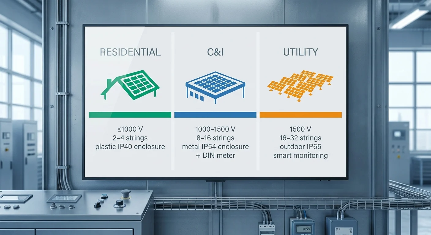
The enclosure specification, component count, and monitoring requirements for a PV DC overvoltage protection box scale directly with system voltage, string count, and installation environment. A 5 kW residential rooftop needs only basic DC SPD Type 2 and string fusing in a compact plastic enclosure, whereas a 2 MW utility ground-mount demands IP65-rated metal cabinets, multi-pole DC MCBs rated for 1500 VDC, and remote monitoring of surge-counter status. Below we compare the typical bill-of-materials and enclosure choices across three common deployment scenarios.
In all three scenarios, the SPD voltage protection level (Up) must remain below the inverter's maximum input voltage, and the DC MCB breaking capacity must exceed the prospective short-circuit current of the array at STC. For utility projects subject to grid-code requirements, additional arc-fault detection or insulation-monitoring devices may be mandated; consult local standards and inverter manufacturer datasheets during the specification phase.
How to Specify and Source a PV DC Protection Box from TPKELE
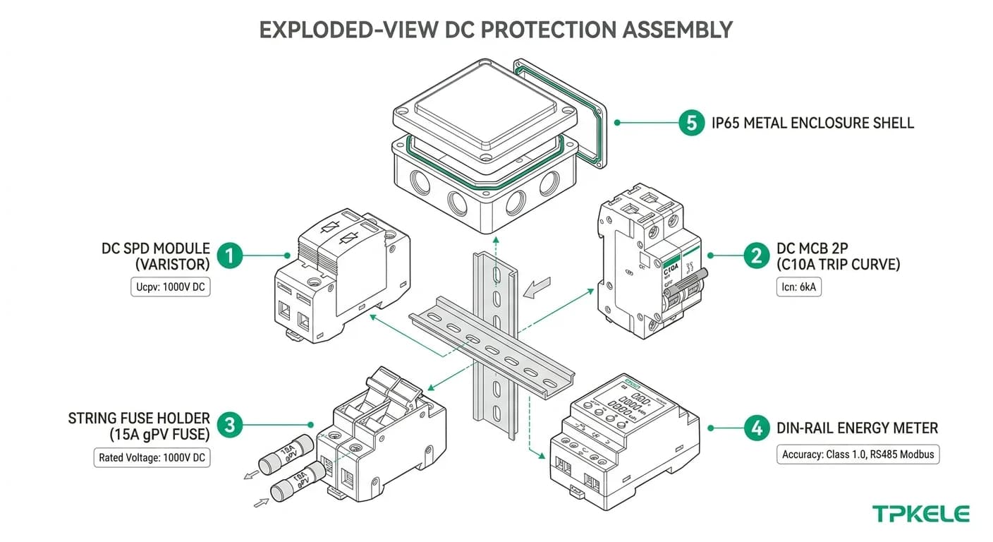
Sourcing a PV DC protection box requires more than matching a catalogue number to a system voltage. The enclosure must integrate DC SPDs, string overcurrent protection, and a DC isolator whose ratings are mutually consistent and traceable to the same IEC or AS/NZS framework used by your local authority having jurisdiction (AHJ). Working through the five steps below before raising a purchase order will eliminate the most common mis-specifications — undersized Uc, mismatched fuse holders, and enclosures rated IP54 where the installation demands IP65.
DC Surge Protection
TPKELE DC SPD Series
Type 2 and Type 1+2 DC surge protective devices for PV applications, rated up to 1 500 V DC. CE-marked, compliant with IEC 61643-31. Datasheets and Declaration of Conformity available on request.
For non-standard string counts, utility-scale busbars, or enclosure configurations outside the standard range, TPKELE's engineering team can provide a factory drawing and quotation. Specify your system voltage, string count, and target IP rating when you enquire.