PV DC Combiner Selection Guide

How to Specify a PV DC Combiner Box: Strings, Voltage, and Protection

3 min read

PV DC combiners bring multiple array circuits into a defined output arrangement, but the required protection and enclosure depend on the system design. This guide will compare common configurations and identify the information buyers should provide before requesting a quotation.

Compliance note: PV DC combiner boxes are configured to project specifications; enclosure, protection, and approval requirements depend on the installed components and final application. Buyers must verify the complete assembly’s documentation and applicable EU, Australian/New Zealand, or North American requirements before ordering.

What a PV DC Combiner Does

A PV DC combiner is installed between the PV strings and the inverter's DC input. It provides a defined point for string connections and, where the design calls for it, combines multiple string circuits into one or more output circuits. The assembly may also incorporate string overcurrent protection, DC isolation, and surge protection. Its configuration depends on the array layout, inverter inputs, and applicable installation requirements.

Complete assemblyThe specified combination of enclosure, terminals, internal wiring, busbars, and fitted protection or switching devices.
EnclosureThe housing that accommodates the components and provides the specified environmental protection; it is not, by itself, a complete combiner.
Individual devicesFuses, disconnectors, and surge protective devices perform specific functions. Their individual ratings do not establish the rating of the complete assembly.

When reviewing a combiner specification, identify both the installed components and the ratings of the assembled unit. In particular, confirm the number of inputs and outputs, maximum DC voltage, current ratings, and enclosure protection rating for the specific model. An enclosure rating or a device datasheet alone does not describe the complete combiner configuration.

Inside a Typical Combiner

A typical layout starts with separately identified string inputs and ends at output terminals sized for the combined circuit. Between them, the design may include string overcurrent protection, a DC isolating device, surge protection, and monitoring connections. Their presence and ratings follow the array design and applicable installation rules; the list is not a mandatory bill of materials for every combiner. IEC 62548-1 addresses PV array wiring, protection, switching, and earthing provisions. ([webstore.iec.ch](https://webstore.iec.ch/en/publication/110893?utm_source=openai))
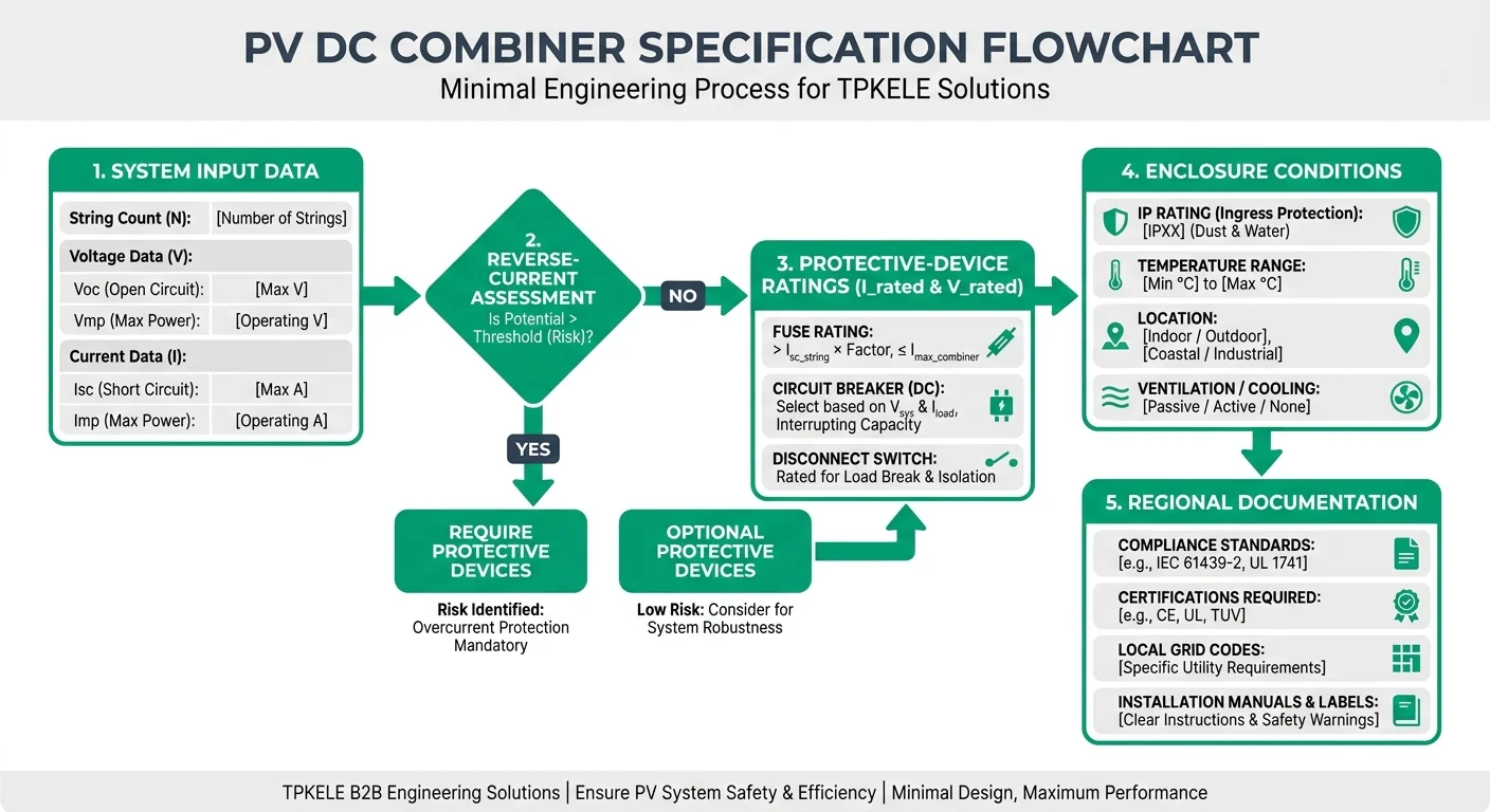
String inputsSpecify the number of inputs, connector or terminal arrangement, cable sizes, polarity identification, and maximum design voltage.
Output terminalsSpecify the number of outputs and terminal capacity against the calculated combined current and outgoing conductor size.
Overcurrent protectionWhere the design requires string protection, specify the protected conductors and device ratings. PV fuse-links are covered by IEC 60269-6; the need for them must be established from the array design. ([webstore.iec.ch](https://webstore.iec.ch/en/publication/68843?utm_source=openai))
IsolationIf isolation is to be provided inside the enclosure, define its location, pole arrangement, DC voltage and current ratings, and operating requirements. IEC 60947-3 covers switches and switch-disconnectors; confirm suitability for the specific device. ([webstore.iec.ch](https://webstore.iec.ch/en/publication/59785?utm_source=openai))
Surge protectionWhere the surge assessment calls for a DC-side SPD, define its PV voltage rating, protection arrangement, and coordination requirements. IEC 61643-31 covers SPDs for the DC side of PV installations. ([webstore.iec.ch](https://webstore.iec.ch/en/publication/26931?utm_source=openai))
Optional monitoringIf required, define which strings or outputs need current measurement, status indication, or communications, together with auxiliary power and signal interfaces.
Confirm the actual circuit arrangement
A switch, fuse, or SPD installed elsewhere in the system should not be assumed to be inside the combiner. Provide a single-line diagram showing device locations and the intended isolation boundary when specifying the enclosure. Confirm final component ratings and assembly requirements for the specific configuration and destination market.
Product Anatomy
img-1

Common Combiner Configurations

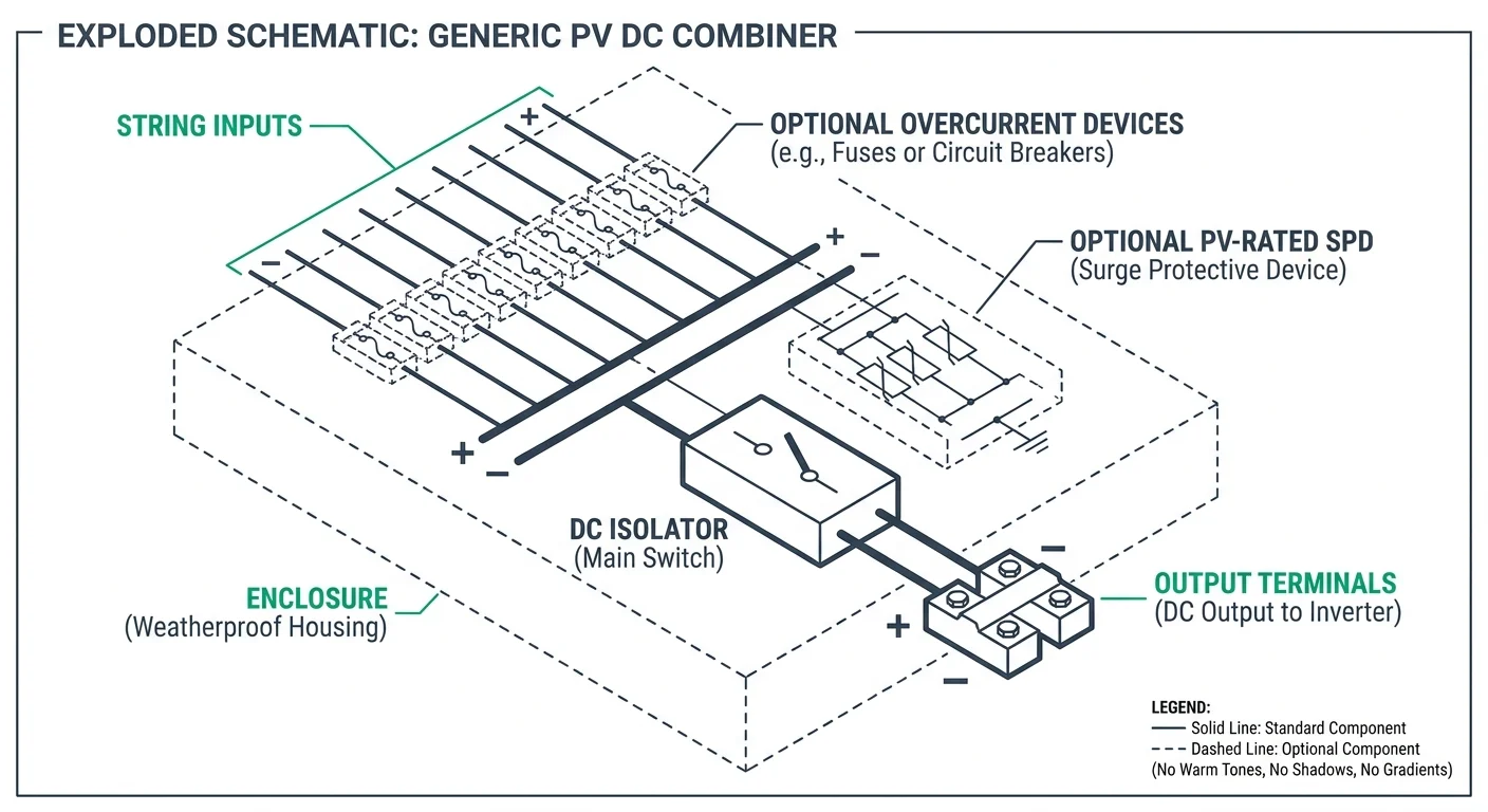
Select the configuration from the array design, not the string count alone. The decision depends on whether parallel strings can drive reverse current into a faulted string, the module’s maximum series fuse rating, and the protection already provided elsewhere in the DC circuit. IEC 62548-1 addresses PV array wiring and electrical protection; IEC 61439-2 includes provisions for assemblies used in PV installations. For approval, identify the applicable requirements in the destination market and request evidence for the specific assembly configuration. ([webstore.iec.ch](https://webstore.iec.ch/en/publication/110893?utm_source=openai))
Fused combinerDesign condition: Use string-level overcurrent protection where the calculated reverse-current exposure or applicable installation requirements call for it.Protective function: Appropriately rated DC fuses protect individual string circuits; specify any required DC isolation and surge protection separately.Approval documents: Provide the string count, module and inverter data, maximum calculated DC voltage, current calculations, proposed fuse ratings, single-line diagram, and component and assembly rating evidence.
Unfused combinerDesign condition: Consider only when the array design demonstrates that string-level overcurrent protection is not required.Protective function: Combines circuits without string fuses; any required isolation and surge protection must still be specified.Approval documents: Provide the reverse-current assessment, module maximum series fuse rating, conductor ratings, single-line diagram, and evidence supporting the proposed protection arrangement.
Monitored combinerDesign condition: Specify when string-level current data or fault indication is needed for operation and maintenance; monitoring may be added to a fused or an unfused design.Protective function: Monitoring reports operating conditions but does not replace required overcurrent protection, isolation, or surge protection.Approval documents: Provide the underlying protection calculations plus the monitoring channel count, measurement requirements, communications protocol, auxiliary-power requirements, and wiring diagram.
Approval is configuration-specific
Ask for the assembly drawing, rated DC voltage and current, enclosure rating, component schedule, and applicable verification or certification documents for the exact proposed build. Availability and approval of each feature must be confirmed for the specific model and destination market.
Comparison Infographic
img-2

Specifications to Confirm Before Selection

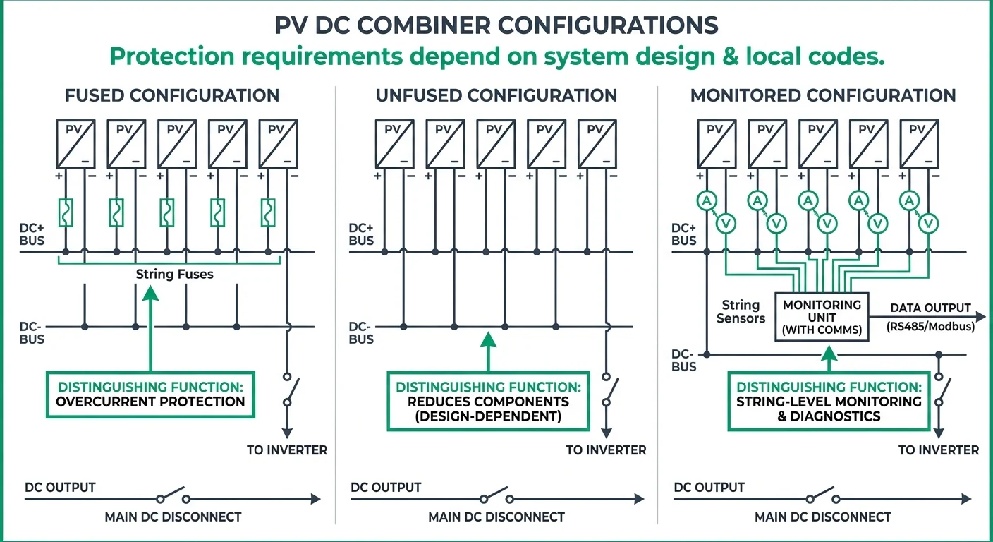
Provide the array layout and site conditions with the quotation request, not just a nominal combiner voltage and string count. The supplier needs the module data, inverter input limits, and circuit arrangement to assess conductor and protection ratings. Confirm the following values for each combiner location, particularly where arrays with different orientations or module types are involved.

SpecificationInformation to provideSelection check
String countNumber of incoming strings, required outgoing circuits, and any planned spare inputs.Confirm terminal positions and whether strings are combined into one output or kept in separate groups.
Maximum DC voltageModule open-circuit voltage, modules in series, and the site's minimum design temperature.Use the temperature-corrected maximum array voltage to check the ratings of every DC component; do not rely on nominal system voltage alone.
Current and reverse currentModule short-circuit current, strings in parallel, module maximum series fuse rating, and applicable design factors.Check output current and conductor ratings separately from possible reverse current into a faulted string; determine whether string overcurrent protection is required under the applicable installation rules.
Fault ratingsCalculated prospective fault current at the installation point and the required DC protective-device arrangement.Confirm DC breaking capacity, voltage rating, and any polarity or connection restrictions for the specific devices proposed.
Enclosure protectionIndoor or outdoor location, mounting position, ambient temperature range, and exposure to water, dust, UV, or corrosion.Specify the required installed IP rating under IEC 60529 and confirm enclosure material and environmental suitability for the site.
Cable entriesIncoming and outgoing cable quantities, outside diameters, conductor sizes, entry direction, and termination requirements.Confirm gland sizes, entry spacing, bending space, and that the completed entries maintain the required enclosure protection.
Verify the complete assembly
A component rating does not establish the rating of the assembled combiner. Request the proposed assembly's rated DC voltage and current, protective-device specifications, and installed IP rating for the exact configuration. Confirm applicable local installation requirements and suitability of the specific model before approval.
Selection Flowchart
img-3

Applications from Rooftops to Ground-Mount Arrays

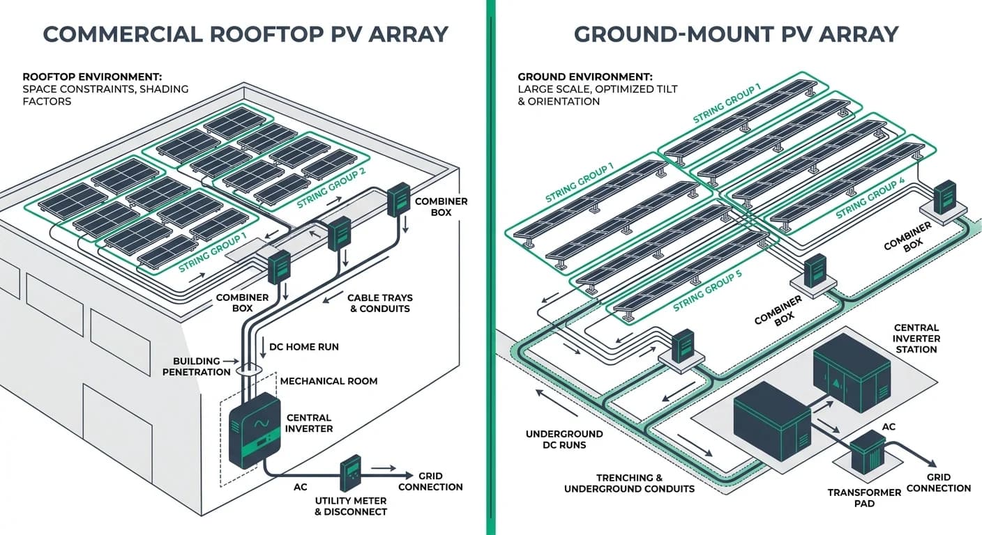
The installation layout determines where string circuits converge and whether a separate combiner is needed. Roof area, cable routes, and inverter location affect the practical number and placement of enclosures. Exposure, maintenance access, and the level of string-level monitoring required can then change the enclosure and internal arrangement.

Small rooftop systemsA separate combiner may be unnecessary when a small number of strings connect directly to suitable inverter inputs.If installed outdoors, assess roof access, solar exposure, cable entry orientation, and the enclosure rating required at the mounting location.
Large commercial rooftopsStrings spread across multiple roof zones may be grouped near their source to organize cable runs to the inverter.Confirm safe maintenance access and whether operations staff need circuit identification or string-level monitoring.
Ground-mount arraysDistributed array rows can require multiple field-mounted combiners, with output circuits routed toward central equipment.Specify for site-specific dust, rain, temperature, and UV exposure, and consider how technicians will isolate and inspect each field location.

For any layout, place enclosures where cable routing remains practical and technicians can reach them without creating an avoidable access hazard. Monitoring requirements should be stated explicitly: total output measurement and individual string measurement call for different provisions. Final enclosure and component suitability must be confirmed against the specific installation conditions and equipment model.
Application Diagram
img-4

Regional Documentation and Approval Checks

Request a documentation package for the exact combiner configuration, including its model reference, drawing revision, and component schedule. Assembly ratings and approval evidence should match the quoted string count, DC voltage, current ratings, and installed protective devices. A certificate for an individual component does not establish compliance of the complete combiner assembly.

Assembly drawings and component scheduleRequest a single-line diagram, internal wiring diagram, general arrangement, terminal schedule, and bill of materials with manufacturer and part references. Drawings should identify polarity, earthing and bonding, cable entry provisions, and any required external protection.
Component ratings and application limitsObtain datasheets for fuse links and holders, switching devices, SPDs, terminals, and other installed equipment. Check DC voltage, current, breaking capacity or short-circuit rating as applicable, temperature derating, and permitted conductor sizes. Confirm ratings for the specified pole connections and PV earthing arrangement.
Assembly verification and production testsRequest the declared assembly standard, supporting verification records, and routine verification or production test records. Where IEC 61439-1 and IEC 61439-2 are specified, request evidence covering applicable requirements such as temperature rise, dielectric properties, protective circuits, short-circuit withstand, and enclosure protection. Evidence should identify the assembly or design family covered and any limits on configuration changes.
European Union documentationRequest the EU Declaration of Conformity identifying the exact product, applicable legislation, and standards used, together with marking and installation instructions. Ask for supporting technical evidence relevant to the quoted configuration. CE marking is a manufacturer declaration of conformity; any separate third-party certificate should be checked for its scope and model coverage.
United States and Canada approval evidenceConfirm the assembly certification or field evaluation route required by the project and authority having jurisdiction. For the United States, request the relevant NRTL listing information where required; for Canada, request certification acceptable to the provincial or territorial authority. Verify the complete assembly designation, applicable standard, certification record, and conditions of acceptability.
Australia and New Zealand documentationRequest evidence supporting the applicable assembly requirements, including AS/NZS 61439.1 and AS/NZS 61439.2 where specified, and installation information needed for compliance with AS/NZS 5033. Confirm any applicable supplier registration, declaration, or marking obligations for the destination and equipment classification. These requirements must be confirmed for the specific model and supply arrangement.

Before purchase, reconcile the quotation, drawings, nameplate details, and approval records against the same configuration. Check certificate numbers and model coverage with the issuing body where verification is available, and resolve substitutions before release for manufacture. TPKELE certification status, available test evidence, and destination-market acceptance must be confirmed for the specific model.

Send Your Combiner Specification

For a configuration review, submit your single-line diagram and string data, including the number of strings, maximum DC voltage, and string current. State the installation location and destination market so the enclosure requirements and applicable documentation can be reviewed against the project conditions. Any proposed device ratings or approvals must be confirmed for the specific configuration.

Submit your PV combiner requirements

Send the single-line diagram, string data, installation location, and destination market for a configuration review.

Contact TPKELE

Technical disclaimer: This guide provides general technical principles for product selection and application. Final specifications must be determined by a qualified electrical engineer based on actual site conditions, local electrical codes, load characteristics, and installation environment. TPKELE is not liable for damages resulting from improper product selection, installation, or use. Always verify compliance with applicable standards (IEC, UL, AS/NZS, etc.) and consult local authorities before installation.

Need help on this product family?

Send your project list - we will reply within one business day.