What Is an AC MCB and How Does It Operate?
An AC miniature circuit breaker (MCB) is an automatically operated electromechanical switch designed to protect low-voltage AC circuits (typically up to 440 V AC) from damage caused by overload and short-circuit currents. Unlike fuses, which must be replaced after operation, MCBs can be manually reset after tripping, making them a reusable protection solution. They are manufactured to meet IEC 60898-1 (for household and similar applications, rated current up to 125 A) or IEC 60947-2 (for industrial applications, with higher breaking capacities). MCBs are fundamental components in residential distribution boards, commercial switchgear, and industrial control panels.
Thermal-Magnetic Tripping Mechanism
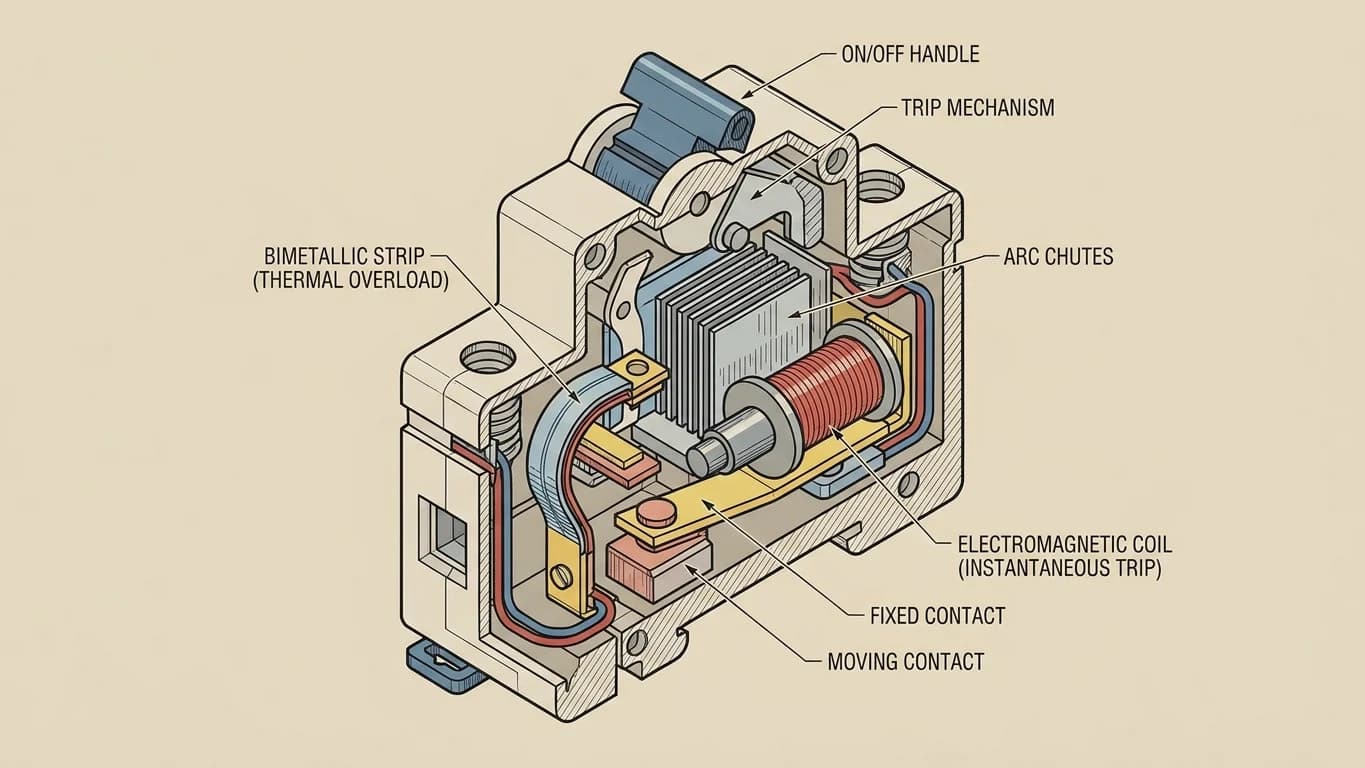
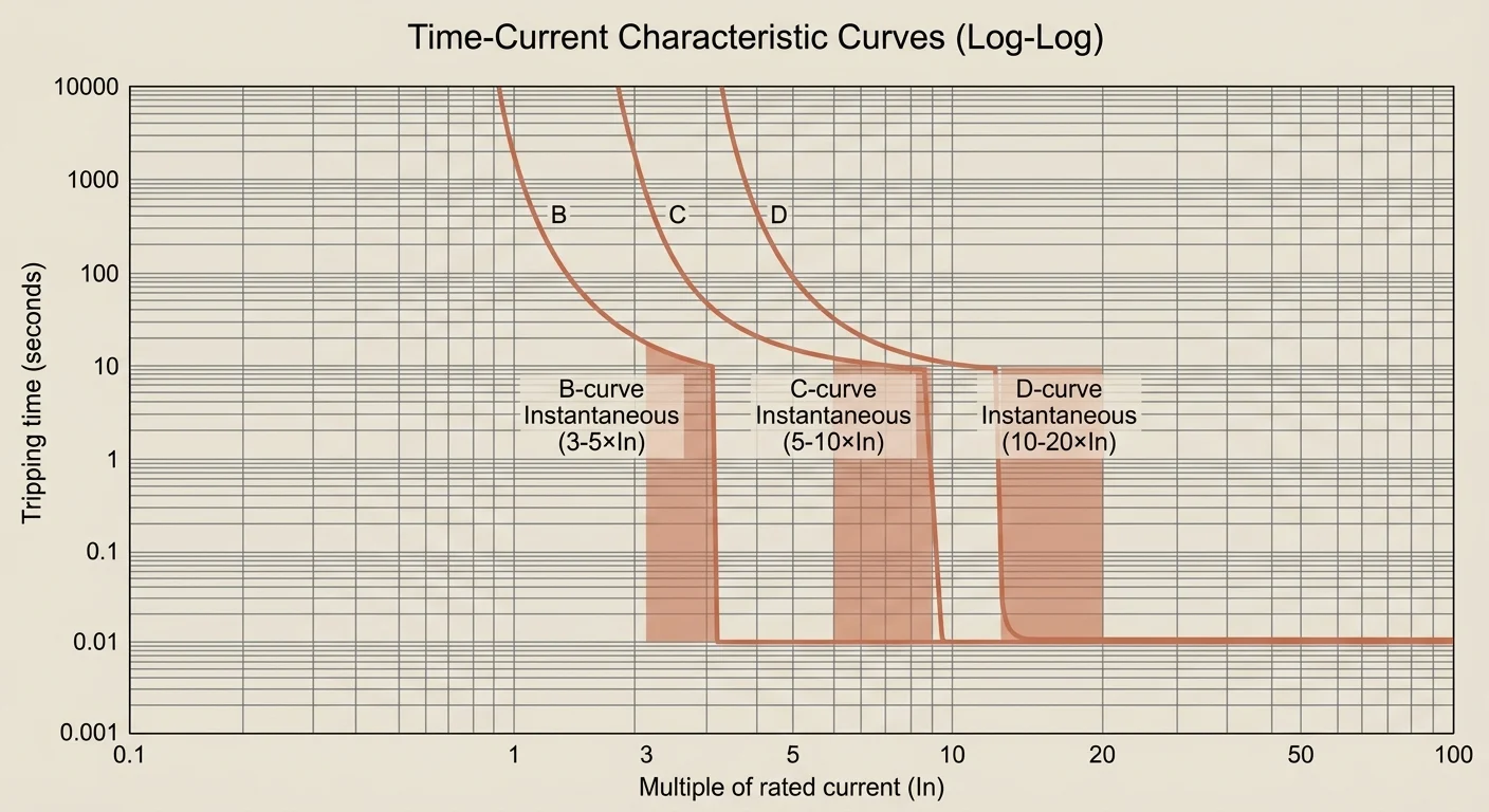
MCBs employ a dual-protection mechanism combining thermal and magnetic trip elements. The thermal trip consists of a bimetallic strip that bends under sustained overload current due to resistive heating; this provides inverse-time protection, where higher overloads trip faster. The magnetic trip uses an electromagnet that acts instantaneously when short-circuit current exceeds a preset threshold (typically 3–20× rated current, depending on curve type), mechanically releasing the trip latch. This dual mechanism ensures coordinated protection: slow, controlled tripping for overloads that allows temporary inrush currents, and rapid disconnection for fault conditions that could cause arcing or conductor damage.
Single-Pole vs. Multi-Pole Construction
MCBs are available in single-pole (1P), double-pole (2P), three-pole (3P), and four-pole (4P) configurations to match different AC distribution topologies. Pole count determines how many conductors are simultaneously disconnected during a trip event. All poles share a common internal trip mechanism, ensuring that a fault in any protected conductor triggers disconnection of all poles simultaneously.
- 1P MCB: Protects single-phase circuits; switches only the line (phase) conductor. Neutral remains connected. Common in 120 V or 230 V branch circuits where neutral is grounded at the panel.
- 2P MCB: Simultaneously disconnects both line and neutral (in single-phase systems) or both phases (in split-phase or phase-to-phase systems). Required when neutral must be isolated, or for 230 V loads in 120/240 V split-phase installations.
- 3P MCB: Protects three-phase loads (motors, industrial equipment). All three phase conductors are switched; neutral is not interrupted. Standard for 400 V or 480 V three-phase distribution.
- 4P MCB (3P+N): Disconnects all three phases plus neutral. The neutral pole typically does not carry a trip element (only switching function) unless specified as a fully rated 4P device. Used where code requires neutral disconnection or in IT earthing systems.
Key Ratings and What They Mean
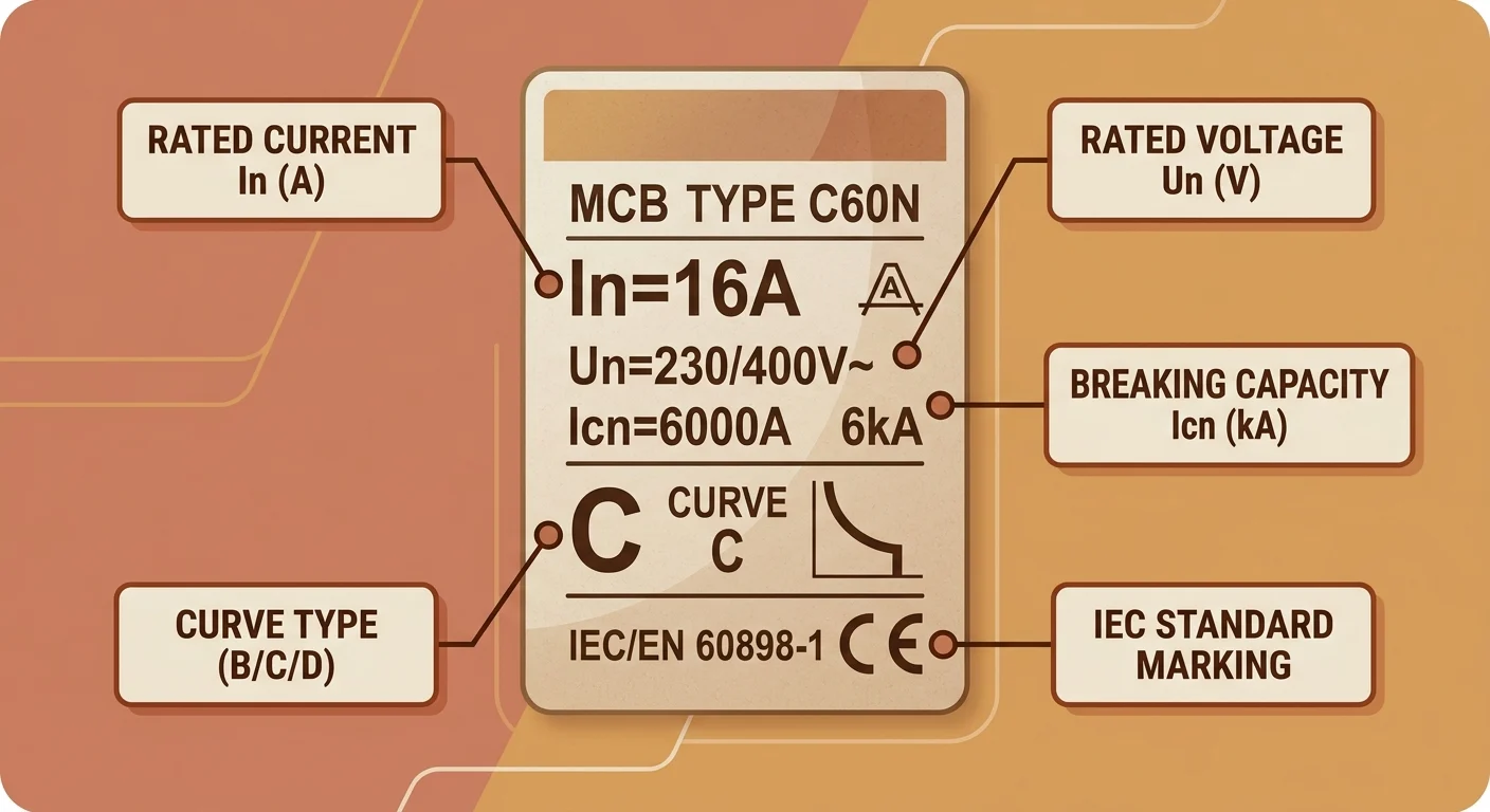
Every MCB nameplate carries a set of ratings that define its operational limits and protective capabilities. These parameters—rated current, voltage, breaking capacity, and utilization category—are not arbitrary: they are derived from type tests conducted per IEC 60898-1 (for household MCBs) or IEC 60947-2 (for industrial MCBs). Misreading these values can result in undersized protection, nuisance tripping, or catastrophic failure under fault conditions. Below is a breakdown of the four core ratings and their practical implications for circuit design.
When selecting an MCB, always cross-reference the prospective short-circuit current (PSCC) at the installation point with the device's Icn or Icu. If the PSCC exceeds the MCB's breaking capacity, back-up protection (e.g., upstream MCCB or fuses) must be coordinated, or a higher-rated MCB must be specified. For installations subject to EN 60947-2 (industrial), verify that the MCB's Icu meets or exceeds the calculated three-phase fault level, including motor contribution if applicable.
IEC 60898-1 vs EN 60947-2: Standard Compliance
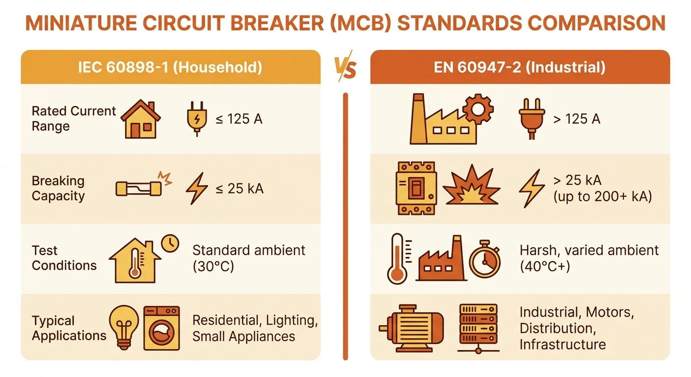
Two product standards govern AC miniature circuit breakers, and they define different devices for different users. IEC 60898-1 covers circuit-breakers for overcurrent protection in household and similar installations, designed to be operated by ordinary persons with no maintenance. IEC 60947-2 covers circuit-breakers for industrial applications and for equipment installed and maintained by instructed or skilled persons. CENELEC adopts both as European Norms (EN 60898-1 and EN 60947-2), and the same split appears in Australia and New Zealand as AS/NZS 60898.1 and AS/NZS 60947.2. Because the scopes and test regimes differ, the standard a device is certified to determines where it can legitimately be installed — not the physical resemblance of the housing.
| Aspect | IEC / EN 60898-1 | IEC / EN 60947-2 |
|---|---|---|
| Typical application | Residential and similar final circuits | Industrial distribution, machinery, switchgear and controlgear assemblies |
| User profile | Ordinary persons | Instructed or skilled persons |
| Rated voltage | Up to 440 V a.c. | Up to 1000 V a.c. / 1500 V d.c. |
| Rated current | Up to 125 A | Manufacturer-declared, no standard limit |
| Short-circuit performance | Icn (rated), verified by a fixed test sequence | Icu and Ics, with Ics declared as a fraction of Icu |
| Trip characteristic | Types B, C, D; calibrated at 30 °C | Manufacturer-declared curves; reference calibration temperature declared by the manufacturer |
| Adjustability | None; settings sealed | Optional — Ir, Ii and short-time delay on category B devices |
| Verification emphasis | Type tests including a long-duration reliability sequence and endurance checks | Type tests plus declared discrimination and back-up protection tables for system selectivity |
The marking on the device tells you which performance regime has been verified. A breaker to EN 60898-1 carries its rated voltage, rated current, Icn in a rectangle, the trip curve letter, the energy limiting class where declared, and the certification body's mark. A device to EN 60947-2 instead declares Icu, Ics and, where relevant, the utilisation category and setting ranges. Both EN 60898-1 and EN 60947-2 are harmonised standards under the EU Low Voltage Directive 2014/35/EU, so CE marking alone does not indicate which one applies. When a drawing or panel schedule is silent on the point, resolve it with the designer before ordering; the datasheets in our AC MCB range state the applicable standard and declared short-circuit data per catalogue number, and type-test evidence for a specific rating can be confirmed against the certificate reference.
Coordination with Upstream and Downstream Devices
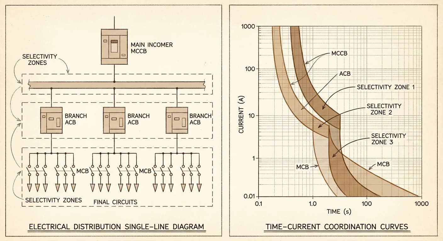
An MCB selected on its own ratings is only half the design. In a distribution board, several protective devices sit in series between the supply and the final circuit, and their operating characteristics must be arranged so that a fault is cleared by the device closest to it, with the minimum of disruption and without any device being asked to break more fault current than it is rated for. This is coordination, and it rests on two separate requirements: selectivity between devices in series, and back-up protection where a downstream device cannot handle the prospective short-circuit current on its own. Installation standards — IEC 60364 / HD 60364 in Europe, AS/NZS 3000 in Australia and New Zealand, and the NEC in North America — all require the designer to demonstrate that the arrangement works, but they leave the method and the evidence to the device manufacturer.
Selectivity and the Selectivity Limit Current
Selectivity, or discrimination, means that an overcurrent on a final circuit trips only the MCB of that circuit, leaving the rest of the installation energised. The practical measure is the selectivity limit current, often written Is: below this fault current the upstream device holds while the downstream device trips; above it, both may operate and the selectivity becomes partial rather than full. Selectivity is hardest to guarantee at high prospective fault currents, because the instantaneous (magnetic) trip bands of the two devices overlap. Two MCBs of the same curve type separated by a modest rated-current step will usually discriminate at low fault currents but not at the top of the board's fault level, so the ratio of rated currents alone is not sufficient evidence.
- Current selectivity — the downstream device trips fast enough at its rated current that the upstream device never reaches its own threshold. Cheap, but limited by the overlap of instantaneous bands.
- Time selectivity — the upstream device is deliberately delayed. Common between an MCCB incomer and MCB ways in industrial boards; a short-time delay or a higher instantaneous threshold upstream.
- Energy selectivity — the downstream device limits the let-through I²t below the upstream device's thermal threshold. In practice this is a property of the specific device pair, established by test rather than by calculation.
- Manufacturer selectivity tables give the maximum permissible upstream/downstream combinations and the resulting Is. Ratios in the region of 1.5:1 to 2:1 between upstream and downstream rated currents are often quoted as a starting point for same-curve MCBs, but the applicable value must be read from the table for the exact devices used.
Back-Up Protection Where the Downstream Rating Is Exceeded
Not every device in a board needs the fault level of the incoming supply. Back-up protection (also called cascading) allows a device with a lower rated breaking capacity to be installed downstream, provided an upstream device is proven to clear the fault and the combination has been tested together. IEC 60947-2 addresses this as coordination between a circuit-breaker and another short-circuit protective device, with the associated tables and conditions in its annexes; IEC 60898-1 approaches the same situation through the concept of conditional short-circuit capacity, where an MCB is tested in combination with a specified upstream protective device rather than alone. In North American practice the equivalent mechanism is the series combination rating permitted by UL 489 and recognised by the NEC for specific tested pairings.
Two conditions apply whenever back-up protection is claimed. First, the upstream device must interrupt the fault within its own rating while the downstream device merely withstands the let-through energy for the duration — so the pair, not the device, carries the evidence. Second, the arrangement must be a tested combination: mixing brands or substituting a different upstream device invalidates the manufacturer's table, and the prospective short-circuit current at the downstream terminals must still be calculated. Where a combination is not covered by published data, the downstream device must instead be selected with a breaking capacity equal to the fault level at its point of installation. For specifiers working with mixed-brand boards or unusual fault levels, the correct step is to request the selectivity and back-up tables for the exact catalogue numbers — our engineering team can supply the applicable combinations against a stated fault level.
Installation Considerations and Derating
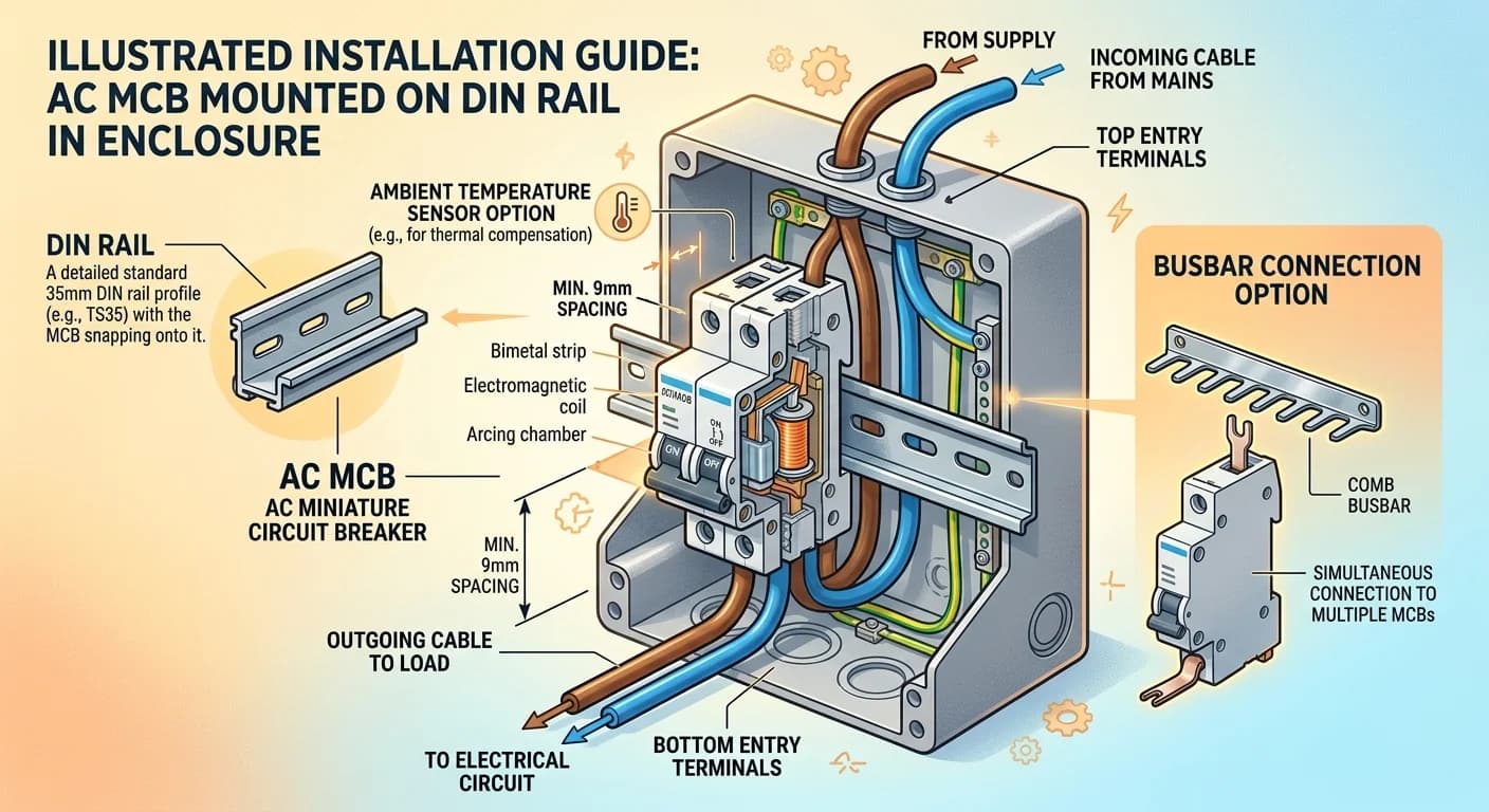
An MCB's published ratings assume a reference ambient temperature of 40 °C and a specific mounting arrangement as defined in IEC 60898-1 Clause 8.6. Deviating from either condition — through elevated enclosure temperatures, tight grouping of loaded breakers, or non-standard orientations — reduces the effective continuous current capacity and must be accounted for during panel design. Ignoring derating is one of the most common sources of nuisance tripping and premature bimetal fatigue in service.
| Ambient Temperature (°C) | Typical Derating Factor | Notes |
|---|---|---|
| 25 | 1.03 – 1.05 | Slight uprating; verify with manufacturer datasheet |
| 30 | 1.00 – 1.02 | Near-reference; no significant correction needed |
| 40 | 1.00 | IEC 60898-1 reference condition |
| 45 | 0.94 – 0.96 | Apply where enclosures operate above ambient |
| 50 | 0.88 – 0.92 | Common in tropical climates or sealed steel enclosures |
| 55 | 0.82 – 0.86 | Confirm with specific model datasheet |
| 60 | 0.76 – 0.80 | Industrial environments; consult manufacturer |
DIN rail mounting to EN 60715 (35 mm × 7.5 mm top-hat rail) is the standard for residential and light industrial MCBs covered by IEC 60898-1. The breaker should snap firmly onto the rail with no lateral play; a loose fit increases contact resistance at the busbar interface and can cause intermittent faults under vibration. For bolt-on busbar connections — typical in industrial switchgear rated under IEC 60947-2 — torque the terminals to the manufacturer's specified value, generally 2–3 N·m for 6 mm² terminations, and confirm cable size compatibility with the terminal block rating. Mixed Al/Cu connections require appropriate bi-metallic terminal hardware to prevent galvanic corrosion.
| Installation Parameter | Requirement / Recommendation | Reference |
|---|---|---|
| DIN rail profile | 35 mm × 7.5 mm top-hat (TH35) | EN 60715 |
| Vertical mounting orientation | Standard; trip mechanism functions normally | IEC 60898-1 |
| Horizontal mounting | Permitted; verify with manufacturer — some bimetal tolerances shift | Manufacturer datasheet |
| Minimum side clearance (grouped MCBs) | Per manufacturer; typically 0 mm between adjacent poles of same product | IEC 60898-1 / manufacturer |
| Clearance from heat sources | ≥ 50 mm from transformers, resistive loads, or power supplies unless thermally modelled | Good practice |
| Cable entry direction | Bottom feed preferred in residential; confirm for specific enclosure layout | Wiring regulations (BS 7671 / NEC / AS/NZS 3000) |
| Terminal torque (copper, 6 mm²) | 2.0 – 3.0 N·m typical; confirm per datasheet | IEC 60947-2 / manufacturer |
Common Failure Modes and Troubleshooting
MCBs are mechanical devices subject to wear, environmental stress, and electrical aging. Field failures typically manifest as nuisance tripping, failure to trip under fault conditions, or mechanical jamming. Understanding these failure modes—and distinguishing between conditions requiring reset versus replacement—is essential for maintaining system integrity and avoiding costly downtime or safety hazards.
Nuisance Tripping: Root Causes
Nuisance tripping refers to breaker operation under non-fault conditions. Common causes include sustained inrush currents (motor starting, transformer energization), harmonic distortion elevating RMS current above rated In, loose terminal connections creating localized heating, or ambient temperature exceeding the MCB's rated operational range (typically –25 °C to +40 °C per IEC 60898-1). Type D curve MCBs may be specified for circuits with high inrush, but if nuisance trips persist, verify actual load current against breaker rating and consider voltage drop or power quality issues upstream.
- Inrush currents: Motors, transformers, and capacitive loads can produce transient peaks 6–10× rated current. Verify trip curve matches load profile.
- Harmonic content: Non-linear loads (VFDs, switch-mode power supplies) increase true RMS current. Use true-RMS instrumentation to measure actual load.
- Loose connections: High-resistance joints generate I²R heating, falsely triggering the thermal element. Torque terminals to manufacturer specification (typically 2.5–3.5 N·m).
- Elevated ambient temperature: Thermal trip threshold decreases with ambient rise. Derate In by 10–15% above 30 °C or improve enclosure ventilation.
Mechanical Wear and Contact Degradation
IEC 60898-1 mandates a minimum mechanical endurance of 4,000 operations (20,000 for certain classes), but contact erosion accelerates under high fault-current interruption or frequent switching. Contact welding occurs when electromagnetic forces during short-circuit events fuse silver-alloy contacts, preventing future trip operation. Visual inspection may reveal pitting, discoloration, or carbonization on contact surfaces. Arc chutes, which extinguish the fault arc, can accumulate carbon deposits that compromise dielectric strength. MCBs subjected to fault currents exceeding 80% of rated Icn should be replaced immediately, as internal damage may not be externally visible.
- Contact welding: Most common after short-circuit interruption at or near Icn. Replace breaker; do not attempt to force reset.
- Arc chute fouling: Carbon buildup reduces interrupting capacity. Replace MCBs in high-fault or frequent-switching applications every 5–7 years.
- Mechanical binding: Operating mechanism may jam due to dust ingress or internal spring fatigue. If manual reset requires excessive force, replace the unit.
- Trip-free mechanism failure: Loss of trip-free function (inability to hold breaker closed under fault) indicates internal mechanical failure; immediate replacement required.
When to Replace vs. Reset
A single thermal trip due to temporary overload (e.g., simultaneous appliance startup) typically does not damage the MCB; allow the bimetal to cool (5–10 minutes) and reset. Magnetic trips caused by short-circuit faults require investigation before reset. If the breaker has interrupted a fault current approaching or exceeding its rated Icn, replacement is mandatory per IEC 60898-1 Annex B, as the interrupting capacity may be compromised. Breakers older than 10–15 years, or those in corrosive/high-temperature environments, should be replaced during planned maintenance regardless of trip history. Maintain a log of trip events, including date, estimated fault magnitude, and corrective action taken.
| Condition | Action | Rationale |
|---|---|---|
| Single thermal trip, no recurrence | Cool 10 min, then reset | Bimetal returns to normal state; no internal damage expected |
| Magnetic trip (short circuit) | Investigate fault, replace if I<sub>fault</sub> > 0.5 I<sub>cn</sub> | High fault currents cause contact erosion and arc chute degradation |
| Repeated nuisance trips | Measure load current, verify connections, upsize if needed | May indicate sustained overload, loose terminal, or harmonic content |
| Trip after fault current ≥ I<sub>cn</sub> | Replace immediately | IEC 60898-1 Annex B: breaker may have exhausted interrupting capacity |
| Visible arcing, burning smell, or contact discoloration | Replace immediately, inspect upstream for fault source | Internal damage compromises safety and interrupting performance |
| Breaker age > 15 years or harsh environment | Replace during planned maintenance | Mechanical parts and contact surfaces degrade over time |
TPKELE AC MCB Range and Technical Support
TPKELE's AC MCB lineup covers 1P, 1P+N, 2P, 3P, and 4P configurations with rated currents from 6 A to 125 A. Breaking capacity spans 6 kA (Icn, IEC 60898-1) for residential and light commercial applications up to 10 kA for industrial distribution boards where prospective short-circuit current demands higher interrupting performance. Trip curve variants — B, C, and D — are available across the range, allowing engineers to match the breaker characteristic to load type without over-specifying. Exact model availability, frame assignments, and accessory compatibility (auxiliary contacts, shunt trip, undervoltage release) should be confirmed against the current product datasheet for each specific part number.
Engineering Support
Specify the Right MCB for Your Project
Submit your load schedule, prospective short-circuit current, and installation category. TPKELE's engineering team will confirm curve selection, verify coordination with upstream devices, and provide relevant test documentation.