AC Surge Protection Selection Guide

Type 1 vs Type 2 SPD: Tests, Ratings and Installation Positions (2026 Guide)

4 min read

Type 1 and Type 2 SPDs are distinguished by their intended application and test classifications, not simply by which device has a higher current rating. This guide will help buyers and panel engineers compare test waveforms, protection ratings and installation positions, then prepare a model-specific specification for quotation.

Compliance note: AC SPD requirements are addressed by IEC 61643-11:2025 and UL 1449; AS 1768:2021 addresses lightning protection system design in Australia. Buyers must verify the specific model's applicable test reports, EU conformity documentation, Australian approval or RCM requirements where applicable, or North American listing, as well as local installation rules before purchase. ([webstore.iec.ch](https://webstore.iec.ch/en/publication/65314?utm_source=openai))

Why the Type 1 vs Type 2 Distinction Matters

An SPD cannot be selected by comparing discharge-current figures alone. The first question is which standard and installation position the specification addresses: IEC 61643-11 classifies AC SPDs by test class, while UL 1449 uses Type designations tied to installation conditions. Treating these labels as interchangeable can lead to a device being specified for the wrong duty or location.

Similar labels, different classifications
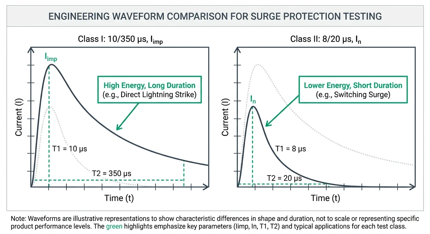
Under IEC 61643-11, Type 1 corresponds to Class I testing, which includes an impulse-current test using a 10/350 µs waveform; Type 2 corresponds to Class II testing using an 8/20 µs discharge-current waveform. Under UL 1449, a Type 1 SPD may be installed on the line or load side of the service equipment overcurrent device, whereas a Type 2 SPD is installed on its load side. An IEC Type 1 designation does not establish a UL Type 1 listing, or vice versa.

For an IEC-based specification, identify the required test class, impulse or nominal discharge-current rating, voltage protection level and intended position in the installation. For a UL-based project, confirm the required UL 1449 Type, installation location and applicable voltage and short-circuit ratings. In either case, confirm the published ratings and approvals for the specific model before placing it on a bill of materials.

How Type 1 and Type 2 SPDs Are Tested

IEC 61643-11 distinguishes Type 1 and Type 2 AC SPDs through different test classes and impulse waveforms. The Class I test uses a 10/350 µs current impulse, while the Class II test uses an 8/20 µs current impulse. Because these waveforms differ substantially in duration and energy, their stated current values cannot be compared as interchangeable performance rankings.

Test characteristicType 1 SPDType 2 SPD
IEC 61643-11 test classificationClass IClass II
Current impulse waveform10/350 µs8/20 µs
Relevant declared currentImpulse discharge current, IimpNominal discharge current, In
What the test evaluatesPerformance under the specified Class I impulse test conditionsPerformance under the specified Class II impulse test conditions
Do not rank Iimp against In
A Type 1 Iimp value and a Type 2 In value describe results from different tests. Specify the required test class and waveform first, then compare declared ratings and test evidence for the particular models under consideration.
Comparison Infographic

Where Each SPD Fits in an AC Installation

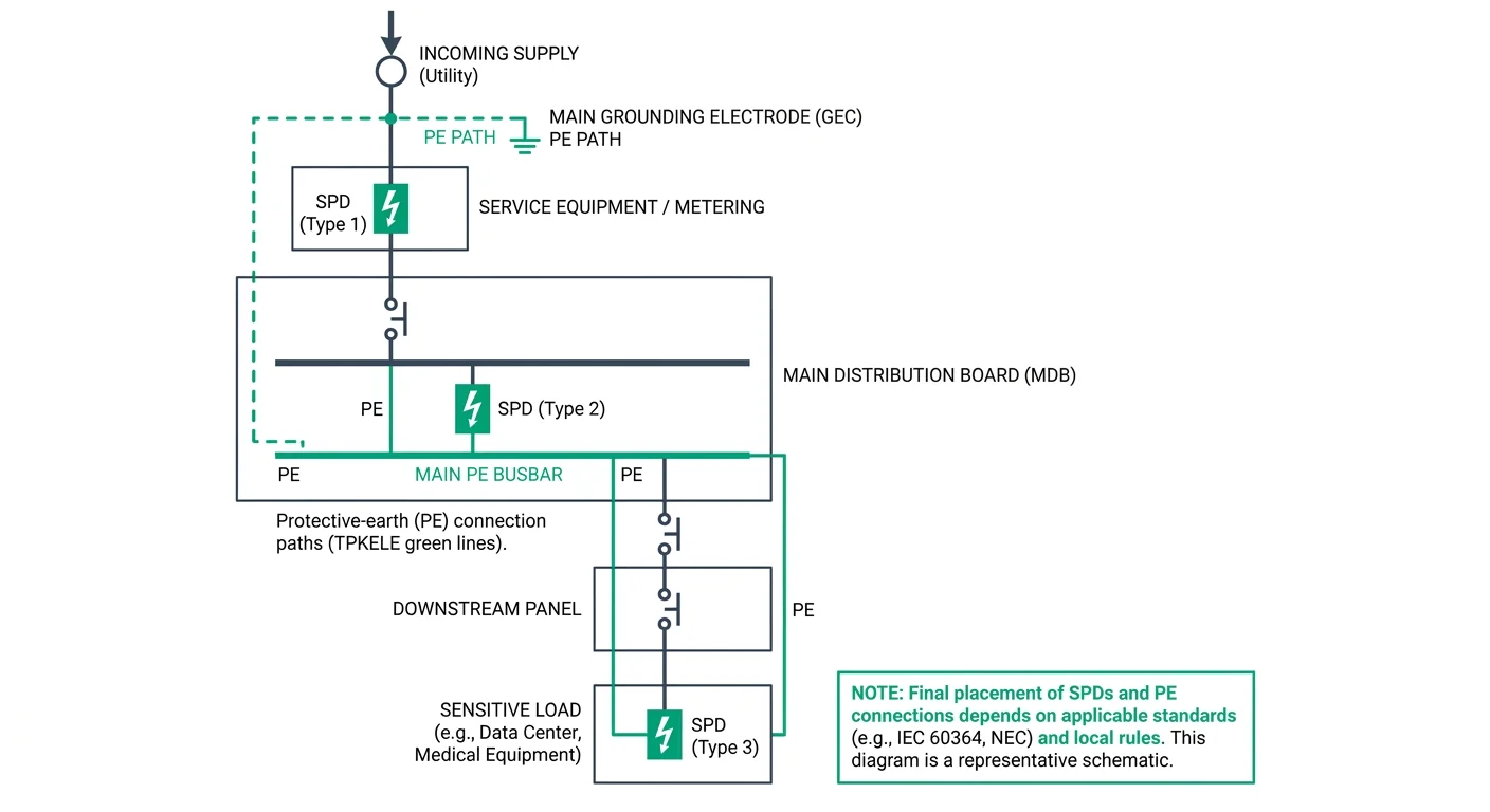
SPD location should be selected from the installation’s exposure, earthing arrangement, incoming supply, and required protection zone—not from the device label alone. A Type 1 SPD is generally considered at the service entrance or main distribution point where part of the lightning current may enter the installation, particularly where an external lightning protection system or overhead supply increases exposure. A Type 2 SPD is normally installed downstream in a main or sub-distribution board to limit switching and residual surge voltages after the service-entry stage.

Service entrance or main distribution boardUse a Type 1 or Type 1+2 SPD when the installation may be exposed to direct or partial lightning current, subject to the earthing system and the applicable national rules.Position the device close to the origin of the installation, with short, low-inductance connecting conductors and suitable upstream overcurrent protection.Confirm the required impulse current rating, voltage protection level, short-circuit withstand, and conductor arrangement from the project risk assessment and the specific product data sheet.
Downstream distribution or final circuit panelUse a Type 2 SPD where the principal requirement is protection against induced lightning effects and switching overvoltages within the installation.Install it in a main distribution board, sub-board, control panel, or other suitable location close to the circuits and equipment requiring protection.Check the system voltage, earthing configuration, backup protection, and the manufacturer’s permitted connection scheme before selection.
Coordinated protection at multiple locationsUse staged protection when the installation is large, has multiple distribution boards, long cable runs, sensitive equipment, or different exposure levels between buildings and panels.A typical arrangement is Type 1 or Type 1+2 at the service entrance followed by Type 2 devices in downstream boards; Type 3 protection may be added close to particularly sensitive loads where required.Coordination must be verified using the manufacturer’s installation instructions, specified cable lengths or decoupling requirements, and the applicable installation standard. Do not assume that two SPDs are coordinated solely because they have different Type classifications.

Exposure assessment should consider overhead or underground supply, lightning protection on the building, local lightning activity, building-to-building cable routes, the length of downstream circuits, and the sensitivity or service continuity requirements of connected equipment. For projects designed to IEC practices, the selection and installation should be checked against IEC 61643-11 and the relevant requirements of IEC 60364-5-53; European, US, Australian, and New Zealand installations may require additional national provisions. The final quotation should state the installation position, system configuration, Uc, protection level, discharge or impulse current rating, backup protection, and coordination method, with values confirmed for the specific model.
Application Diagram

Ratings to Check Before Specifying a Model

Compare the ratings against the installation’s nominal voltage, earthing arrangement and prospective fault conditions. Confirm the applicable SPD product standard and the exact rating definitions on the manufacturer’s datasheet; similar-looking values may use different test waveforms or measurement conventions. The figures below are selection checks, not a substitute for model-specific coordination and installation instructions.
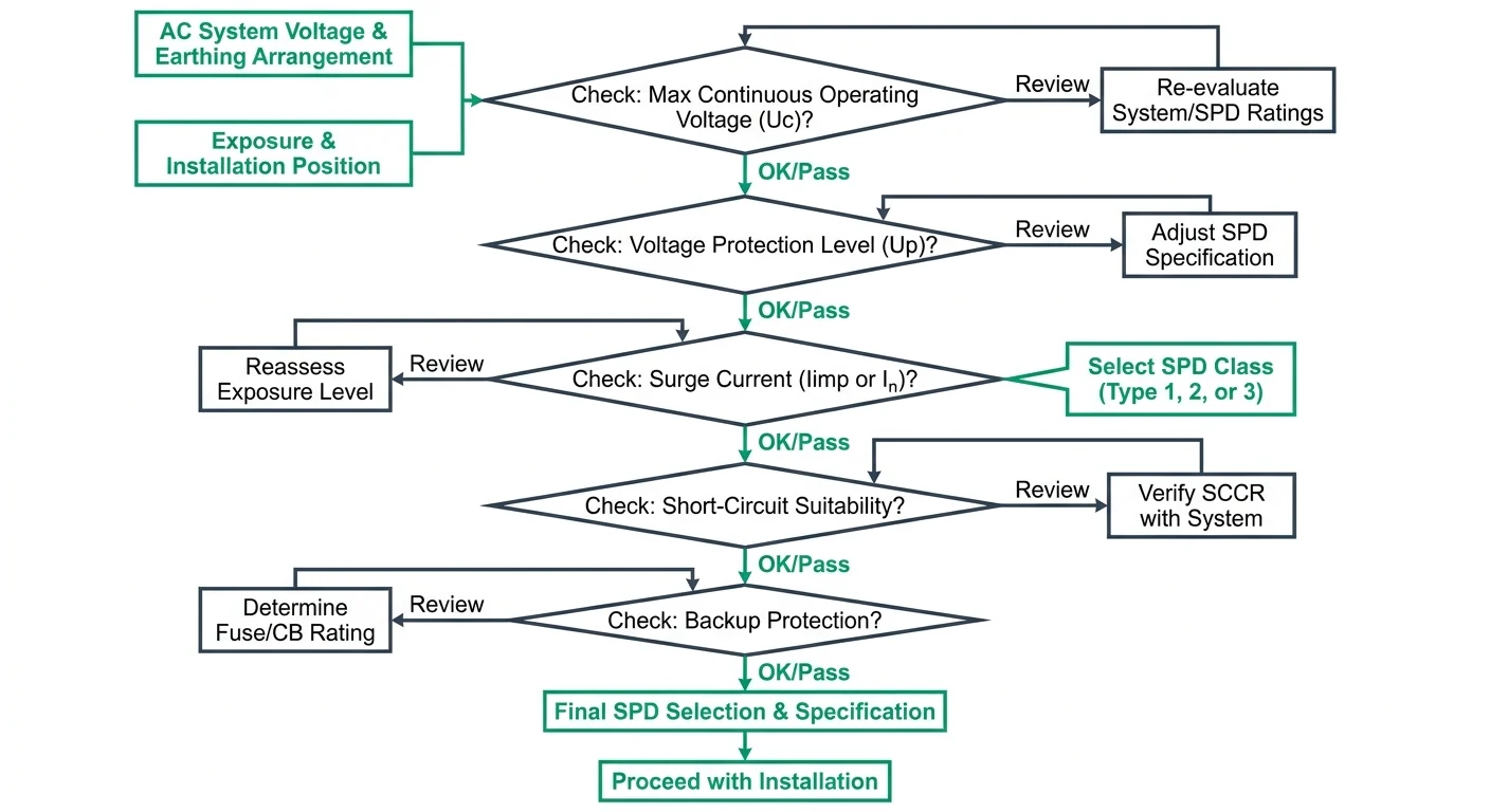
Uc or MCOVMaximum continuous operating voltage: the highest RMS AC voltage, or DC voltage where applicable, that may be applied continuously to the SPD’s protection mode. Select it for the system voltage and earthing arrangement, including credible temporary overvoltage conditions; verify the definition and value for the specific model.
Up or VPRUp is the declared voltage protection level, typically expressed in kV; VPR is a UL voltage protection rating, expressed in volts. They are not interchangeable labels. Check the rating under the applicable standard and compare it with the withstand level of the equipment, allowing for additional voltage drop across connecting conductors.
IimpImpulse current rating associated with the Type 1 test using the 10/350 μs waveform. Check the declared value per pole or protection mode and the required test classification for the application. Do not compare Iimp directly with an 8/20 μs current rating as though the waveforms were equivalent.
InNominal discharge current, typically specified with the 8/20 μs waveform for Type 2 testing. Confirm whether the datasheet states the value per pole or for another configuration, and check any separately declared maximum discharge current (Imax) where relevant.
Backup protectionCheck the specified upstream fuse or circuit-breaker type and maximum rating, plus any conditions under which separate backup protection is required. Follow the SPD manufacturer’s coordination instructions and local installation rules; do not infer compatibility from the SPD current ratings alone.
Prospective short-circuit conditionsVerify the installation’s prospective short-circuit current and the SPD’s declared short-circuit current rating or conditional short-circuit rating, including any required backup protective device. The assembly must satisfy the applicable fault-current and disconnection requirements.
Connection configurationConfirm the supported system and protection modes, such as L-N, L-PE and N-PE, or the manufacturer’s specified multipole arrangement. Check conductor routing, terminal capacity, required disconnector arrangement and the manufacturer’s instructions for the relevant earthing system.
Indication optionsCheck whether status indication is visual, remote-contact, or both; confirm what the indication represents and how remote contacts are wired and monitored. Verify whether replaceable cartridges and a compatible replacement module are available for the selected model.
Confirm against the exact model
Ratings, backup-device limits, short-circuit conditions and connection diagrams vary by model and market. Obtain the current datasheet and installation instructions for the exact configuration; where a value or compatibility condition is not explicitly stated, confirm it with the manufacturer before specifying.
Selection Flowchart

Selection Examples for AC Panels and PV Systems

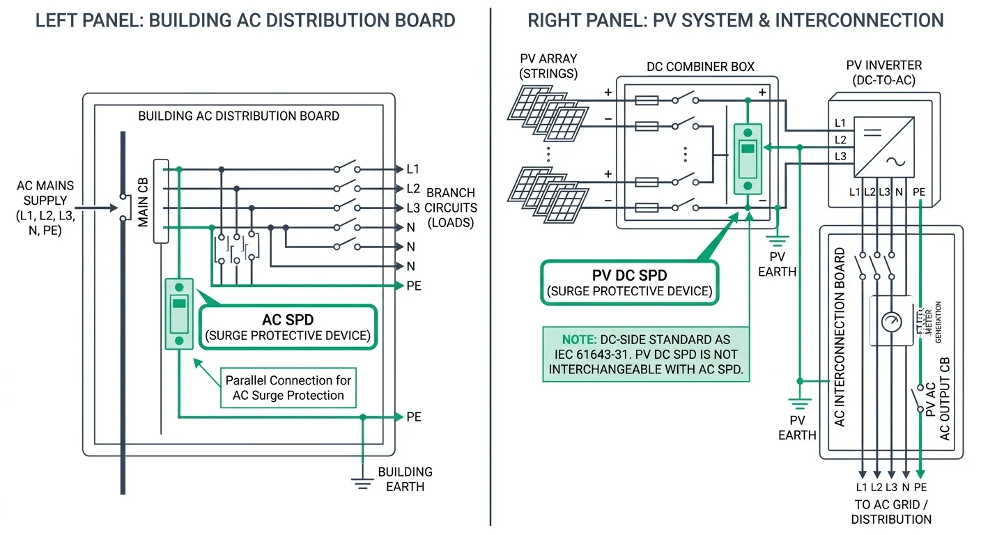
For a building AC distribution board, select the SPD for the supply system, the board’s installation position and the applicable installation standard. A Type 2 SPD is commonly specified at a distribution board where the installation assessment calls for protection against induced surges; a Type 1 or combined Type 1+2 device may be required where the assessed lightning-current risk and installation arrangement call for it. Confirm the required voltage protection level (Up), maximum continuous operating voltage (Uc), short-circuit withstand and backup protection with the specific device data and project requirements.

Application pointSelection focusSpecification notes
Building AC distribution boardAC system voltage and earthing arrangement; Type 1, Type 2 or Type 1+2 classification as required by the installation assessmentState the installation position, required Uc and Up, short-circuit conditions, and any required backup overcurrent protection. Confirm coordination with upstream and downstream protective devices.
PV inverter AC connectionAC supply characteristics at the inverter connection and the protection required for that installation pointSpecify an AC SPD for the AC system and its earthing arrangement. Select its type and ratings from the site assessment and applicable installation requirements; do not infer the required type from the inverter alone.
PV array DC circuitPV DC voltage and current conditions, array configuration, inverter limits, and exposure at the DC installation pointSpecify separately for the DC application. Confirm the SPD's DC operating voltage and ratings, polarity and circuit arrangement, and compatibility with the PV system and inverter using model-specific documentation.
AC and PV DC require separate specifications
An AC SPD is not interchangeable with a PV DC SPD. A PV DC-side device requires a separate, application-specific specification based on the array's maximum system voltage, circuit configuration, inverter limits and applicable installation requirements. Verify all ratings and suitability against the exact device documentation before quotation or installation.
Application Diagram

Documentation and Questions for Suppliers

Request documents for the exact SPD model, pole configuration and voltage variant proposed for the project. A product-family brochure alone does not establish the ratings, test classification or installation requirements of a specific variant. Ask the supplier to identify the applicable standard and the market for which each test report or listing applies.

Model-specific datasheetObtain the full model designation, Type 1 or Type 2 classification, electrical ratings, terminal specifications, dimensions and any required external backup protection.
Test or listing evidenceRequest a report or listing record that identifies the proposed model and applicable standard, such as IEC 61643-11 or UL 1449. Confirm that its scope covers the quoted configuration and intended market.
Wiring diagramRequest the connection diagram for the proposed earthing system and pole arrangement, including protective-device placement and any remote indication contacts.
Installation instructionsObtain the manufacturer's requirements for conductor size, terminal torque, mounting, lead length, backup protection and replacement of plug-in modules, where applicable.
  • Does the evidence identify the exact order code being quoted, including any replaceable module?
  • Are the wiring diagram and installation instructions applicable to the project's supply voltage and earthing arrangement?
  • Which protective device, if any, does the manufacturer require upstream of this specific SPD model?

Review TPKELE SPD Options and Request a Quote

Review the documented AC SPD models at TPKELE AC SPDs before requesting a quotation. Include the system voltage, earthing arrangement and intended installation position in your inquiry. Specify the required SPD type, maximum continuous operating voltage (Uc), voltage protection level (Up) and applicable discharge-current rating; confirm availability and values against the specific model documentation.

AC SPD selection

Compare AC SPD Models

Check model-specific ratings, then request a quote with your electrical system details and required protection ratings.

View AC SPDs

Technical disclaimer: This guide provides general technical principles for product selection and application. Final specifications must be determined by a qualified electrical engineer based on actual site conditions, local electrical codes, load characteristics, and installation environment. TPKELE is not liable for damages resulting from improper product selection, installation, or use. Always verify compliance with applicable standards (IEC, UL, AS/NZS, etc.) and consult local authorities before installation.

Нужен готовый щит? Соберите щит AC с этим компонентом онлайн.

Собрать онлайн →

Нужна помощь по этому семейству продуктов?

Отправьте список проектов — ответим в течение одного рабочего дня.