Device Selection by Application Type
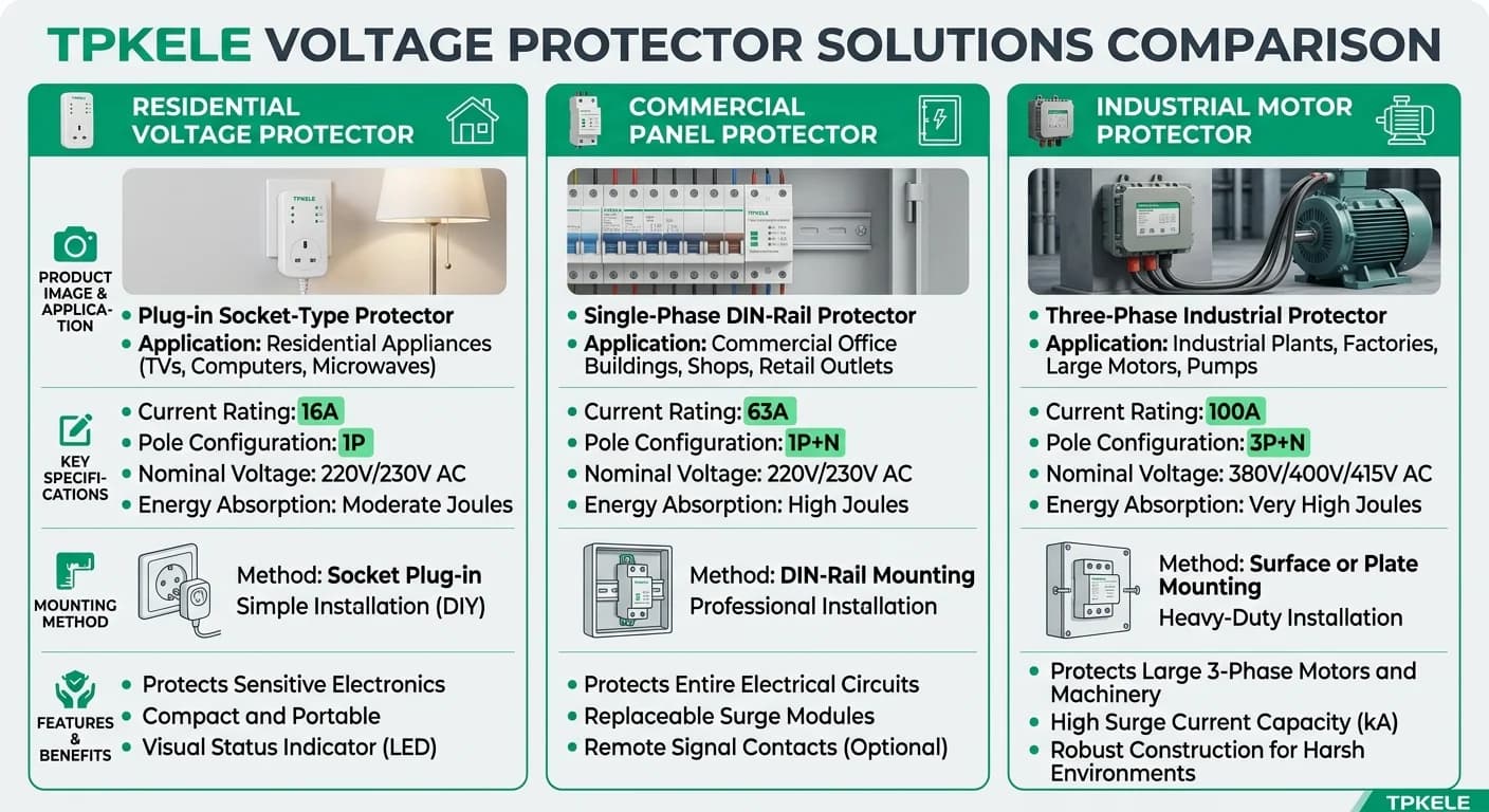
Middle East installations require voltage protectors matched to specific load characteristics and mounting requirements. Socket-mounted devices suit plug-in equipment in commercial fit-outs, DIN-rail models integrate into distribution panels for centralized protection, and three-phase units handle motor-driven systems common in HVAC and industrial applications. Selection depends on load type, installation accessibility, and coordination with upstream protection devices.
Current ratings must account for continuous load plus 25% margin per IEC 60364-5-52 derating requirements. In GCC climates where panel enclosure temperatures exceed 40°C, apply temperature correction factors from IEC 60947-2 Annex A. Three-phase devices require neutral connection even in delta-configured systems to enable asymmetry detection—verify neutral availability during site survey before specifying STATS series units.
Installation Requirements for IEC 60364-Compliant Systems
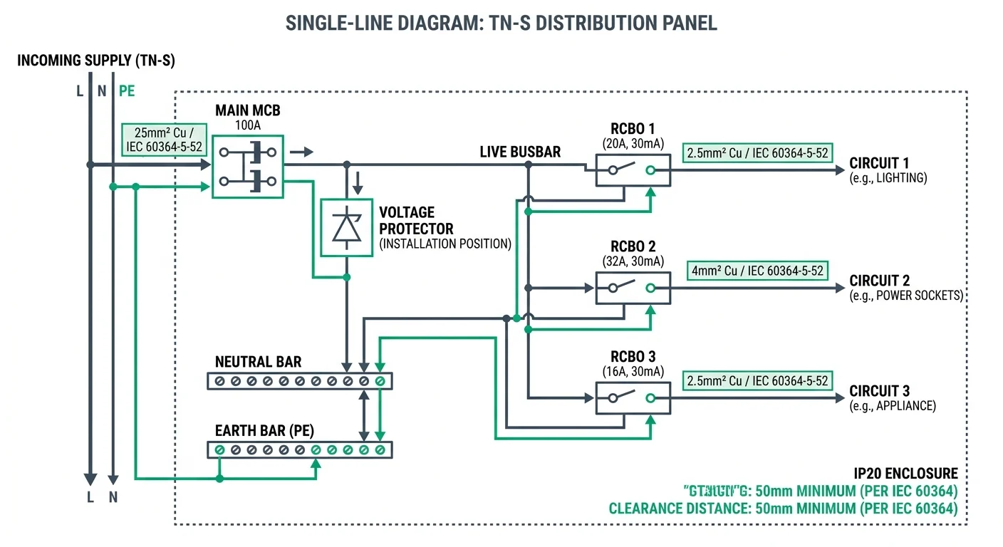
IEC 60364 governs the design and erection of low-voltage installations, and the clauses that matter most for a voltage protector are coordination (60364-4-41 for protection against electric shock, 60364-5-53 for switchgear and controlgear selection and erection) and current-carrying capacity (60364-5-52). In a 230/400 V TN-S or TN-C-S board, the protector must be connected downstream of the incoming main MCB and upstream of the load RCBOs. Placed there, one device supervises the whole downstream installation; placed after the RCBOs it would protect only its own final circuit, and any RCBO trip would also remove the voltage-protection function.
- Confirm the earthing arrangement before wiring: identify TN-S or TN-C-S, verify 230 V phase-to-neutral and 400 V phase-to-phase, and confirm the PEN conductor is not switched or disconnected downstream of the origin.
- Position the protector on the busbar between the incoming main MCB and the first load RCBO, fed from a dedicated branch so that an RCBO trip does not de-energise it.
- Provide short-circuit protection for the protector branch with an MCB or fuse rated at or below the maximum stated in the manufacturer datasheet; the device's own withstand rating is not a substitute for upstream overcurrent protection. Where the exact value is not stated, confirm against the specific model.
- Size phase, neutral and protective conductors to IEC 60364-5-52, including the ambient-temperature correction factor: GCC switchrooms frequently run at 40-45 degrees C, where PVC-insulated copper capacity falls by roughly 10-20 percent against the 30 degrees C tabulated values.
- Keep the wiring routed directly to the terminals with no crossing over adjacent devices, and respect the assembly clearances of IEC 61439-1 where the protector is built into a Type-tested or partially type-tested assembly.
| Circuit | Device rating (In) | Min. conductor, copper/PVC | Remark |
|---|---|---|---|
| Voltage protector branch | 40 A | 10 mm2 | Branch protection must not exceed the datasheet maximum; derate for ambient |
| Sub-main to local distribution board | 63 A | 16 mm2 | Verify voltage drop and disconnection time at the far end |
| RCBO-protected socket final circuit | 16 A | 1.5-2.5 mm2 | Cross-section also governed by maximum earth-fault loop impedance |
| SPD connecting conductors (where fitted) | Not applicable | 6 mm2 or larger | Keep as short and straight as possible; confirm per the SPD datasheet |
Configuration for Common Middle East Load Profiles
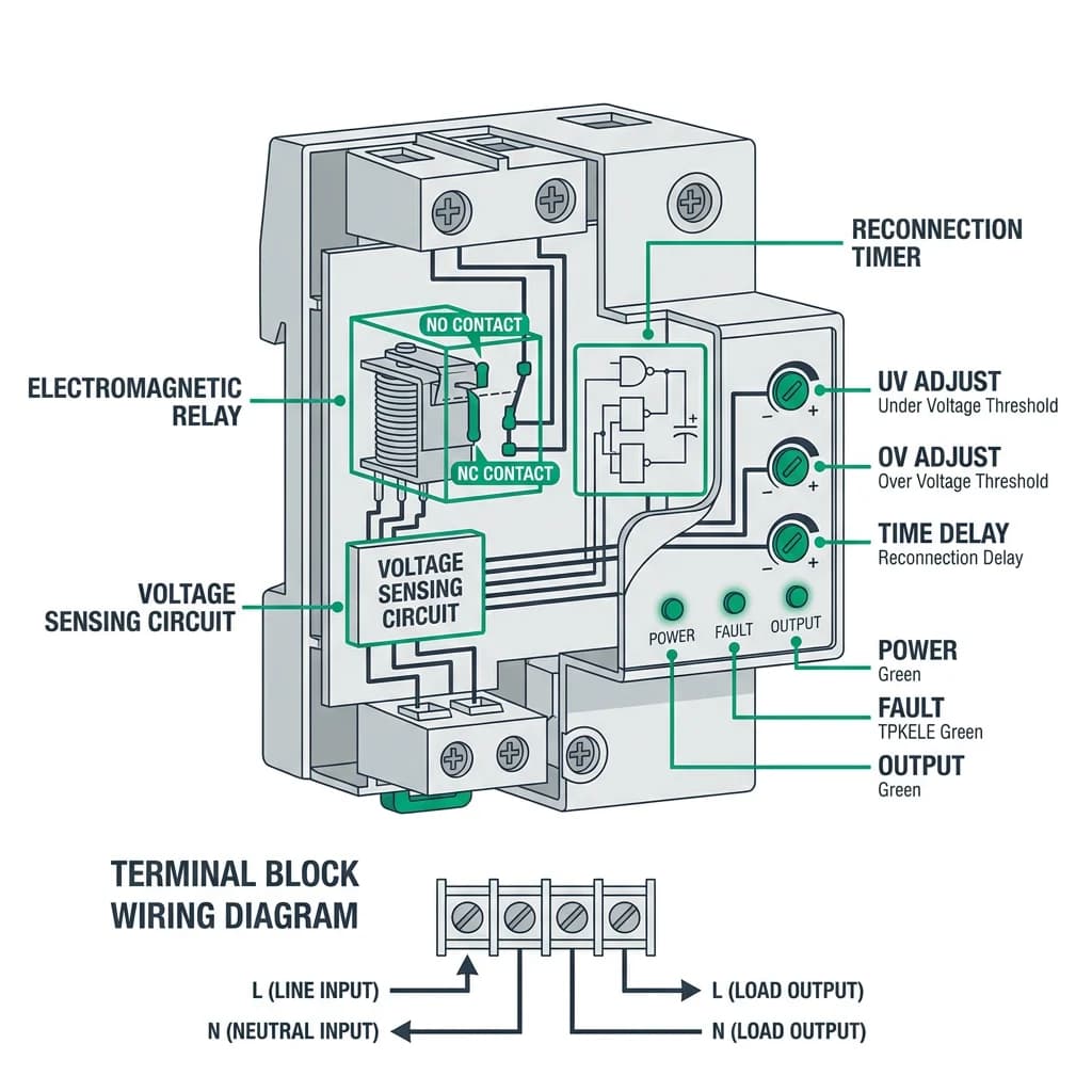
The three profiles below cover the majority of GCC commercial and light-industrial voltage-protection requirements. What separates them is not the device family — in each case a DIN-rail voltage protector at the origin of the installation does the work — but the threshold window and the delay configured on it. Setpoints should be chosen against the tolerance of the connected equipment rather than the widest deviation the standard permits, and must sit inside the adjustable range of the specific model being specified.
| Load profile | System and nominal voltage | Suggested threshold window | Delay setting | Configuration notes |
|---|---|---|---|---|
| Retail unit — POS, back-office IT, LED drivers | Single-phase 230 V, TN-S or TN-C-S | U< ≈ 207 V, U> ≈ 253 V (230 V ±10%) | 3 s | One protector at the origin, downstream of the main switch; serves all single-phase final circuits |
| Villa HVAC — 3-phase condensing units | Three-phase 400 V, TN-S or TN-C-S | U< ≈ 340 V, U> ≈ 440 V (400 V ±15%) | 5 s | Phase-sequence, phase-loss and asymmetry monitoring required in addition to the voltage window |
| Workshop — imported machinery and machine tools | Single-phase 230 V and three-phase 400 V | Adjustable; commonly set U< 180 V, U> 260 V | 3–5 s | Window set to the nameplate tolerance of each machine group; verify adjustability before ordering |
A retail unit on a 230 V supply normally has one voltage protector immediately downstream of the main switch, feeding POS terminals, back-office IT and LED lighting drivers from the same point. The ±10 % window aligns with the 230 V nominal of IEC 60038 and with the input tolerance of switched-mode equipment, while the 3 s delay is short enough that a brief dip does not interrupt trade, yet long enough to prevent the contactor from chattering when the supply is oscillating. Fitting a protector per circuit is unnecessary and produces inconsistent thresholds across the installation; a single device at the origin keeps the whole unit on one reference. Where the store has a three-phase intake and single-phase final circuits, select a device that monitors all three phases and drops the load on any one of them.
For villa HVAC, the constraint is motor starting rather than electronics. A 5 s delay allows the compressor inrush and the resulting supply dip to clear before the protector re-energises the circuit, and a ±15 % window is normally used so that routine starting voltage sag does not nuisance-trip protection that the compressor and its overload already tolerate. Phase sequence and phase-loss monitoring matter more here than narrow voltage limits, because a reversed or lost phase will destroy a scroll or screw compressor within seconds and no voltage threshold will catch it. Some imported machinery in workshops is rated 200–240 V on a 230 V nameplate, and where a wide-range supply stage is fitted the nameplate tolerance may extend to roughly 180–260 V; in that case the protector window is widened to match the machine, not the utility nominal. The practical limit is that a very wide window delays genuine fault disconnection, so groups of machines with different tolerances are usually split onto separate protectors rather than compromising on one setting.