Why DC Surge Protection Matters
PV strings and their long outdoor cable runs can experience transient overvoltages from nearby lightning strikes, even without a direct strike to the array. Switching operations and disturbances coupled through connected equipment can also produce short-duration voltage spikes in battery systems and other DC distribution circuits. These transients may stress inverter inputs, battery converters, charge controllers, and monitoring equipment beyond their insulation or impulse-withstand limits.
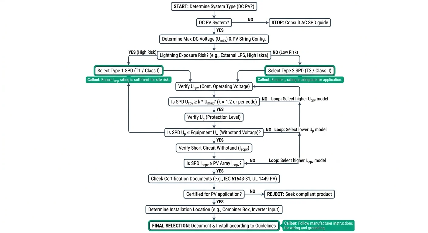
A DC surge protective device (SPD) limits transient voltage at its connection point by conducting surge current through a designated path when the voltage rises above its operating threshold. In PV installations, the relevant product standard is IEC 61643-31 for SPDs connected to the DC side of photovoltaic systems. Effective protection also depends on the installation position, conductor routing, bonding, and coordination with the equipment being protected.
How a DC SPD Diverts Surge Energy
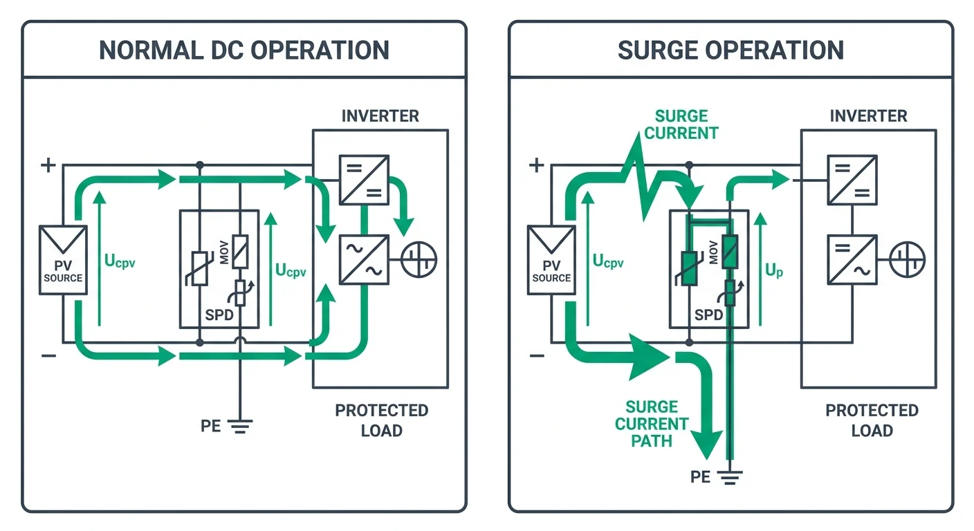
A DC surge protective device (SPD) uses voltage-dependent components, such as metal-oxide varistors or gas-discharge tubes, to limit a transient overvoltage. Under normal operating voltage, the device presents a high impedance and carries little current. When a surge drives the voltage above its operating threshold, the protective components conduct and divert surge current away from the protected equipment. In a PV installation, the discharge path depends on the SPD topology and may run from DC positive or negative to the protective earth (PE) bonding system.
- Bond the SPD PE terminal to the installation's equipotential bonding system; the discharge path must be continuous and suitable for surge current.
- Keep the conductors from the DC circuit to the SPD and from the SPD to PE as short and direct as practicable. Their inductance produces additional voltage during a fast surge, increasing the voltage seen by the equipment above the SPD's stated voltage protection level (Up).
- Assess the complete earthing and bonding arrangement, including connection quality and conductor routing. A low earth-electrode resistance alone does not establish a low-impedance path for a fast transient.
The SPD's published Up is measured under specified test conditions; it is not a guarantee of the voltage at the inverter or other load. Lead length, bonding impedance and installation layout can raise the effective residual voltage at that equipment. For PV applications, check that the selected device is specified for the intended DC circuit and evaluated to IEC 61643-31, then confirm the permitted connection topology in the specific model's installation instructions.
DC SPD Ratings Buyers Must Check
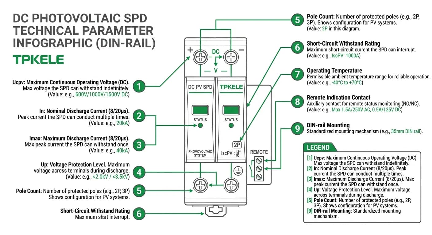
Review the SPD nameplate and datasheet as a set: voltage, discharge-current ratings, protection level, fault-current coordination, and environmental limits must suit the PV array and the installation. Confirm that the stated ratings apply to the relevant DC application and configuration, rather than inferring performance from a product category or a single headline value. For PV SPDs, check the manufacturer’s terminology and applicable product standard; requirements and test classifications can differ by device type and market.
| Quotation check | What to verify | Why it matters |
|---|---|---|
| Voltage selection | Ucpv versus maximum array open-circuit voltage at minimum design temperature | Avoids selecting a device whose continuous-voltage rating is below the array’s design voltage. |
| Surge ratings | In and Imax values, impulse waveform, and the manufacturer’s stated test conditions | Allows like-for-like comparison without treating different ratings as interchangeable. |
| Equipment coordination | Up and the protected equipment’s impulse withstand level; account for connection layout | Checks whether the declared protection level is suitable at the equipment terminals. |
| Fault coordination | Prospective short-circuit current, SPD withstand declaration, and specified backup protective device | Confirms the assembly is suitable for the installation’s fault conditions. |
| Configuration and service | Pole diagram, operating temperature range, and local or remote replacement indication | Confirms fit with the system topology, installation environment, and maintenance requirements. |
Type 1, Type 2 and Combined Protection
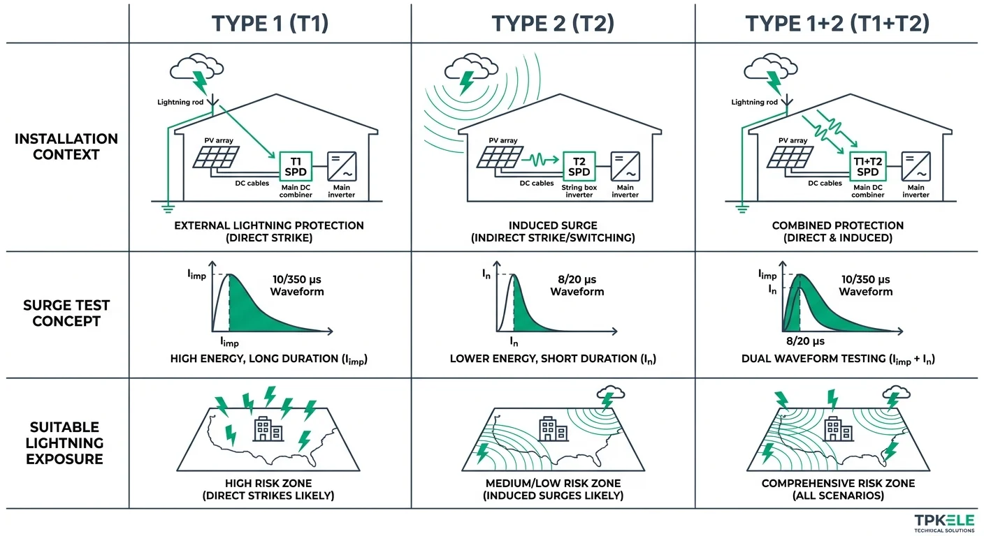
IEC 61643-31 classifies SPDs for photovoltaic installations by their tested protection function. Type 1 devices are intended to conduct partial lightning current where lightning current may enter the installation; Type 2 devices limit induced surges and switching transients. A combined Type 1+2 SPD is tested for both functions, but the correct selection still depends on the PV system layout, lightning protection measures, and the manufacturer's specified installation conditions.
| Arrangement | Lightning exposure and context | Test waveform | Typical PV application |
|---|---|---|---|
| Type 1 | Partial lightning current may enter the circuit; selection is based on the lightning protection assessment and installation conditions. | 10/350 µs impulse current (Iimp) | PV DC circuit requiring Type 1 protection under the project design; exact position and configuration depend on the installation. |
| Type 2 | Induced surges or switching transients; no Type 1 requirement at that point. | 8/20 µs nominal discharge current (In); Imax is specified for the device | PV array or inverter DC side, selected and positioned according to cable routing, equipment layout, and manufacturer instructions. |
| Type 1+2 | Both partial lightning-current exposure and induced or switching surges must be addressed at the same protection point. | Type 1 and Type 2 tests, including 10/350 µs and 8/20 µs waveforms as applicable | PV DC distribution point where a combined device is appropriate; confirm coordination with other SPDs and the inverter. |
Where to Install a DC SPD in a PV System
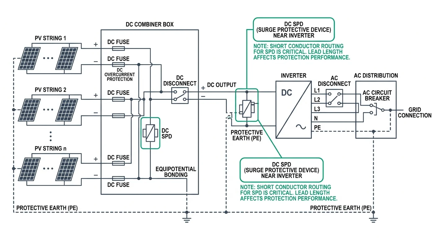
Install DC SPDs at the boundaries where surge exposure or cable length can create a significant voltage difference between equipment and the protective device. In a PV system, typical locations include the array-side DC combiner box and the inverter DC input. The required positions depend on the system layout, lightning protection measures, cable routing, and the installation rules applicable in the target market.
- At the array boundary, place protection near the point where PV strings enter the DC collection or distribution equipment, especially where long outdoor cable runs increase exposure.
- In the DC combiner box, protect the incoming string circuits and consider protection at the box output where the route to the inverter is long or passes through a separate protection zone.
- At the inverter input, install an SPD close to the DC terminals when the inverter is remote from the array or combiner box. Follow the inverter manufacturer's instructions and the applicable PV installation standard.
- Route SPD conductors directly and keep the total connection path between the live conductors, SPD, and PE as short as the equipment design allows. Long or looped leads add inductive voltage during a surge and can reduce the protection achieved at the equipment terminals.
- Where protection is required at more than one location, coordinate devices as parallel protection zones. Check the manufacturer's coordination guidance, cable distance requirements, and ratings rather than assuming that two SPDs will share surge current evenly.
The SPD's backup overcurrent protection must also be coordinated with the DC circuit. Use only the fuse or DC MCB arrangements permitted by the SPD manufacturer, including the specified maximum backup fuse rating and short-circuit withstand conditions. Do not treat a general-purpose AC MCB as suitable for a PV DC circuit; verify DC voltage, polarity, interrupting capacity, and the device's intended application.
Compliance and Project Verification
Check the requirements of the destination market and the specific PV installation before approving a DC SPD. A product standard establishes how the device is tested; an installation standard governs how protection is applied in the system. A claim of IEC compliance does not, by itself, establish a UL listing or compliance with Australian installation requirements. Verify all evidence against the exact model and configuration being supplied.
| Standard | Relevance to a PV DC SPD | Approval check |
|---|---|---|
| IEC 61643-31 | Requirements and test methods for SPDs connected to the DC side of PV installations. | Request test evidence covering the specified model and its declared PV ratings. |
| IEC 60364-7-712 | Installation requirements for solar photovoltaic power supply systems. | Confirm that the proposed protection arrangement is consistent with the project design and applicable installation rules. |
| UL 1449 | US safety standard for surge protective devices. | For US projects requiring a listed device, verify the listing, device type and DC/PV application against the exact model. |
| AS/NZS 5033 | Australian and New Zealand installation and safety requirements for PV arrays. | Confirm the array-side SPD arrangement against the applicable project design and local requirements. |
Specify the Correct DC SPD
Before requesting a quotation, prepare a short specification based on the PV array, installation position, and destination market. Record the maximum expected DC voltage and the required Ucp, discharge-current ratings, Up, and pole configuration. For a PV-side SPD, request model-specific documentation against IEC 61643-31 rather than assuming that a product-family description establishes conformity for every variant. ([webstore.iec.ch](https://webstore.iec.ch/en/publication/26931?utm_source=openai))
PV DC surge protection
Review TPKELE DC SPDs
View the DC SPD product page, then submit your project requirements for model-level specifications and quotation support. Confirm ratings and documentation for the specific model offered. ([tpkele.com](https://www.tpkele.com/products/dc-spd))